Beam Line Detectors Shift
Contents
Collimator and Radiators
Move Collimator
- Ask MCC for beam to be turned off.
- Open Hall-D CSS EPICS Control, if not already available, following instructions.
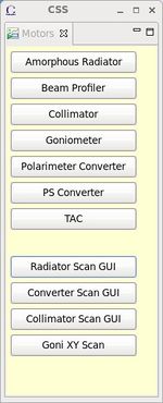
- From Main Action Bar, click Motors in BEAM section. This will open the motor main GUI (Figure 4).
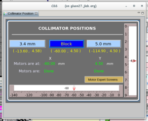
- Click Collimator to bring up the Collimator Control GUI (Figure 1).
- Click the button corresponding to the desired location to move the collimator (GlueX nominally runs on 5mm aperture). Wait until the Motor is Done.
- Make a log entry to HDLOG.
Move Radiator on Amorphous Radiator Stick Assembly
- Ask MCC to turn the beam off. Also ask them to "mask the FSD on the amorphous radiator motion".
- Open Hall-D CSS EPICS Control, if not already available, following instructions.
- From Main Action Bar, click Motors in BEAM section. This will open the motor main GUI (Figure 4).
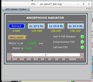
- Click Amorphous radiator to bring up the radiator Control GUI (Figure 2).
- Click the button corresponding to the desired location to move the radiator (you will see a confirmation dialog window). Wait until the Motor is Done and the desired position button is highlighted.
- If you just put a radiator or a wire into the beam, make sure that the GONIOMETER is in BLANK or RETRACTED position.
- Request MCC to "restore the FSD on the amorphous radiator motion".
- Make a log entry to HDLOG.
Move Radiator on the Goniometer
- Ask MCC to turn the beam off. Request that the 5C00 dumplette be inserted into the beam. You can see the status of the 5C00 dumplette in the upper right corner of the main GlueX EPICS GUI.
- From Main Action Bar, click Motors in BEAM section. This will open the motor main GUI (Figure 4).
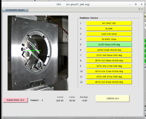
- Click Goniometer to bring up the Goniometer Motor Control GUI (Figure 3).
- Click on the position that is needed. There will be a confirmation window asking if the beam is off and the 5C00 dumlpette is in. Once confirmed, the goniometer will start moving and you should be able to see it in the camera view on the same GUI. If the goniometer does not move on the camera view, please contact the beamline expert. While goniometer is moving there should not be any beam bleed-through. If there is indication of bleedthrough such as high tagger or beam halo monitor counting rates, check with MCC if the dumplette at 5C00 is inserted.
- Wait until the goniometer motion is complete and the desired radiator button is highlighted in green. The green cross-hair also should be pointing to the radiator that you just inserted into the beam. If it points to some other radiator, please contact the beamline expert.
- If the desired radiator is a diamond for coherent bremsstrahlung you will also need to set the proper polarization plane using the CBREM GUI. First one needs to open the CBREM GUI as described in the subsection below. Then one can select the desired orientation by clicking on PARA or PERP buttons on the CBREM GUI. Once the motors reach the right angles the GUI will display the correct polarization plane. Note that you will not be able to observe any motion on the goniometer GUI since the motion are very small and very slow.
- If you just put in a radiator into the beam, make sure that the amorphous radiator stick is in RETRACTED position.
- Make a log entry to HDLOG.
Switching between PARA and PERP orientation of the same diamond
This sections describes the situation when the diamond does not need to be changed, and the "0/90" and "45/135" spatial orientation of the same diamond is not being switched. These situations are described in Move Radiator on the goniometer subsection. In order to simply flip from PARA to PERP orientation or visa versa:
- Call MCC and request to take the beam away for a few minutes. There is no need to mask FSDs or insert the dumplette at 5C00.
- Open CBREM GUI as described in corresponding subsection
- On the newly opened screen, Figure 11, click on PARA or PERP yellow buttons, whichever orientation you are trying to set.
- The motor positions for yaw or pitch, or both angles, indicated on the CBREM GUI will start to change. Once the desired polarization plane shows up in green color under the "Polarization Plane" label on the CBREM GUI, the desired polarization orientation is already set.
- Call MCC and request the beam back at the nominal beam current for the operations.
- When the beam is back, evaluate the coherent peak on the CBREM GUI, and, if needed, adjust the peak position following the instruction in Adjust coherent edge subsection.
Adjusting the coherent edge
The coherent edge during runs on diamond radiator can be adjusted from the CBREM GUI.
Opening CBREM GUI
On the Main Action Bar click on Motors button. A new screen will pop up showing various buttons for beamline related screens.
- On the newly open GUI (Fig. 4) click on Goniometer button. This will open the Goniometer control GUI (see Fig. 3 ). If the camera becomes frozen, try 'F5' on the keyboard to reload the image.
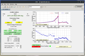
- Click on the CBREM GUI button in the newly opened Goniometer GUI. This will open a new window, see Figure 11, with the buttons that can be used to adjust the coherent edge position.
Adjusting the coherent peak positions
The procedure in this section describes how to adjust the coherent peak position if it is in a range of +-200 MeV within desire edge value. If a larger adjustment is needed or you have a problem adjusting the coherent peak position, please contact the run coordinator (RC) for instructions. Note that the position of the coherent peak can be affected by the beam positions at the 5C11B BPM and at the Active Collimator. Therefore, check the beam positions before trying to adjust the coherent edge as it will drift once the beam positions are restored to their nominal values. Make sure the orbit locks are on and running before trying to adjust the coherent edge. The edge positions can be adjusted by the green arrows under Move/nudge peak label (Figure 11).There are two pairs of these buttons: for large and small nudges to the positions.
- Histograms that calculate the spectrum derivative and edge can be brought up by clicking on the green button 'Start/Restart' in the bottom middle of the CBrem GUI. This starts/restarts the process on the host you are running the CSS session on.
- The blue points of the current peak enhancement histogram should match the red points of the template peak. There is also a blue dashed vertical line showing where the software thinks the peak is and the corresponding coherent edge energy fit value is shown on the GUI under "Coherent Edge Fit Estimate". The blue and red data points should well match each other. Once you think they do, you can fine-adjust the coherent edge position using the fit value. When the red and blue points do not match, then the fit estimate is not reliable.
- Make sure the positions on 5C11B BPM and Inner AC match the nominal values, are stable, and the orbit locks are on. If not, verify from MCC that the position locks for the 5C11B BPM and Inner AC are engaged and let them know the desired positions on AC and on the 5C11B BPM.
- If the coherent peak needs to be moved by more than 100 MeV use the buttons with "<<" or ">>" on it. Once within 100 MeV, use the buttons for small shifts with "<" or ">" on it. Give at least ten seconds after each push of these buttons for the scalers to settle. Also keep in mind that if there is no beam the blue points do not get updated. Therefore, only push the buttons when there is beam. Also you will not be able to see any motion of the goniometer on the web camera in the goniometer motion GUI during these adjustments since the amount of the motion is small and very slow.
- Once the peak is at the desired location, push green Force PARA or Force PERP button, depending what orientation we are supposed to be in, to assign the current motor positions to the setting we are supposed to be in.
- Click Save as defaults green button to save the current setting into the file so that next time the diamond is requested to be in this orientation the newly found motor positions get loaded.
- Take a snapshot of the CBREM GUI with the new positions and make a log entry about the peak adjustment.
Setting Amorphous Reference
The coherent enhancement plot on EPICS CBREM GUI, Figure 11, divides the current tagger scalers by the amorphous reference scalers to enhance the coherent peak. This way the inefficiencies of the tagger counters are canceled in the ratio. It is a good idea to save/update the reference scalers into EPICS every time we run with the amorphous radiator at the nominal beam current. One needs to make sure that there is stable beam at the nominal current and that the scalers in the CBREM GUI are updating when updating the AMO reference scalers. To save the amorphous reference to EPICS one simply needs to push the Save as AMO reference button on the lower graph of the EPICS CBREM GUI, Figure 11. Once the button is pushed the blue points on the upper plot on the lower graph of the EPICS CBREM GUI, Figure 11, should be straight horizontal line at vertical value 1.
Active Collimator
Gains
For standard running, the amplifier gains should be set to 1E-8 A/V. These are now adjusted through CSS
CSS -> Active Collimator -> Set All Gains
The gain of 1E-9 A/V can be used for a radiator of 1E-4 up to 200 nA. If the current or thickness is increased from here, there should be evidence of saturation in the signal. The reported beam position will likely be stuck and the ADC counts seen in the Hall D Active Collimator Diagnostics screen will show counts near 32000.
For a TAC run,
- set the Set All Gains to 10E-10 A/V . The pedestal subtraction always takes place, and the pedestals are usually large for TAC runs. The pedestals are measured when the beam is off and the FSD flag is up. It takes about one minute to measure the pedestals, so there should be a long enough FSD down time for the new pedestals get measured and to kick in. If you are sure that there will be no beam for a few minutes but the FSD flag is not up, you can force the calculation of the pedestals by pushing "Force Pedestal Assignment" choice button to "FORCED" (then pushing the "NORMAL" option on "Force Pedestal Assignment" button when pedestals are assigned).
Halo Counters
Halo counters are PMT-based counters arranged around the beam-pipe to measure the beam halo intensity at various positions along the beam-pipe. the main goal of the halo counters to check the stability of the beam in time and to be used as detectors in beam scanning procedures. If the voltages of the halo counters trip, they need to be restored using the Beamline Voltages GUI that can be opened from the BEAM section of the Main Action Bar .
Radiator Harp Scan
The radiator harp scan is performed to determine the electron beam profile in X- and Y-directions using three wires mounted on the same insertion device that holds the three amorphous radiator. Two of the wires measuring the X- and Y- profiler are mounted at ninety degrees to each other and are inserted into a beam by a stepper motor at 45 degrees with respect to the horizontal plane. The third wire which his measuring the U-profile of the beam is mounted in-between the X- and Y- wires and moves in the direction of the motor. The radiator harp scan is a part of a set of wire scans that also include two accelerator harp scan called 5C11 and 5C11B scans. The last two scans are run by the accelerator and we can request the MCC operators to perform them for us.
Open Radiator Wire Scan GUI
- On the Main Action Bar click on Motors button. A new screen will pop up showing various buttons for beamline related screens.
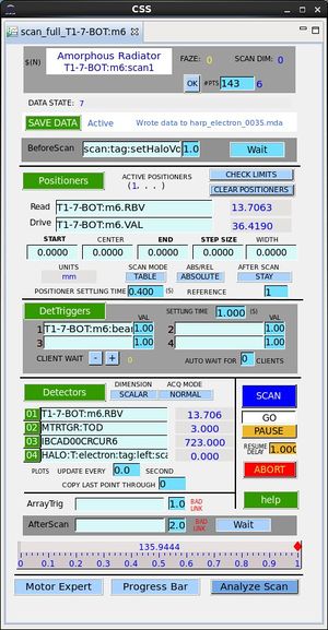
- On the newly open GUI (Fig. 4) click on Radiator Scan GUI button. This will open the radiator scan GUI (see Fig.5 ) that will be used for the radiator scan.
Accelerator Harp Scans
The radiator harp scan is usually combined with the accelerator harp scans in order to be able to project what the virtual beam spot size is at the collimator in the Hall D Collimator Cave. The accelerator harp scan is performed by the machine operators. The accelerator harp scans should be done with the radiators out of the beam and the collimator in blocking position - see the next point. It is important not to change the radiators or make any other beamline configuration changes during accelerator harp scan since the ion chambers FSD might be disabled. After the MCC operator do their scans they post the result in the ELOG and HDLOG logbooks. The important quantities for us are the X-, U- and Y-  -s which are combined with the
  -s obtained from the radiator harp scan to evaluate the beam convergence at the primary collimator.
Preparing for Scans
- Ask MCC to take the beam away for a few minutes and let them know that we are preparing for harp scans.
- When the beam goes away, retract the amorphous radiator and put the goniometer into BLANK or RETRACTED position. There should be no radiator in the electron beamline during the scan. Move the collimator to BLOCKING position.
- Phone the MCC and ask for harp scans using 1 uA of TUNE MODE beam with the 5C11 and 5C11B harps (IHA5C11 and IHA5C11B). Do not move radiators while MCC is performing their wire scans.
- Check that the high voltages for the halo counters are ON in the CSS->BeamlineVoltages EPICS GUI that can be launched from the BEAM section in the main action bar of CSS. The halo counter channels are the ones which have ":HALO:" substring in the Channel Name column on the beamline high voltage GUI.
- Request 200nA of continuous (CW) beam and ask MCC to mask the Ion Chamber and the Hall D amorphous radiator motor from the Fast-Shutdown (FSD). Wait for the beam to come back, verify that the orbit lock on 5C11B beam positions is on, and let beam stabilize at the nominal positions on 5C11B BPM, and then start the harp scan.
Performing the Scan
- Push the blue SCAN button on the radiator scan GUI. The motor will move to the starting position for the scan and start going through the points and acquiring scaler data. The scan automatically pauses when beam goes away and resumes when the beam is detected again. The scan takes about 7 minutes without beam interruptions.
- Periodically check for the messages at the top of the radiator scan GUI. When the last point is acquired, a message Scan Complete will be shown and the motor will stop at that last position (about 90.6). If Scan Complete message does not appear on the top of the scan GUI but you are absolutely sure that both wires scanned the whole beam, you need to push ABORT button on the scan GUI. This will abort the rest of the scan and perform some necessary restoration steps. If you are not sure if the wires went through the beam, either wait for the Scan Complete message or call EPICS expert.
- Note that the motorized stage for the radiator scan (and amorphous radiator) may not retract on his own when the scan is complete. In that case it will need to be retracted using the amorphous radiator EPICS GUI. This should be done with beam off after all scan tasks are done [See "Backout from scan" item #3 below.]
Analyzing Data
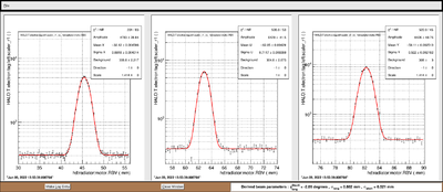
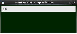
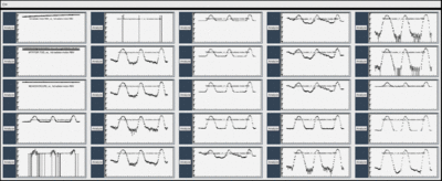
- Once the scan is complete, push Analyze button on the bottom of the radiator scan GUI. This will open a xterm window, a small top window (Fig. 6) and an overview window (Fig. 7) that shows the response of various detectors versus the motor position of the scanner. The main feature of each detector plot is that there are three peaks at different position motors, one for x, one for u, and another one for y. If the peak is not visible for one detector that means that detector is not sensitive to having a wire through the beam and fitting that signal is pretty much useless. Note that the actual screen that shows up may be different from what is shown in Figure 7 since the number of enabled detectors in the scan can be different.
- Select the detector that shows the best signal (usually signal/background ratio is the best indicator) by clicking the corresponding Analyze button. This will open the screen with the fit of the signal. Usually the best ones are those from HALO:T:electron:tag detectors. Note that one can open multiple detector views with the fit to compare. The new screen that pops out will show the results of the fit for the x-profile on the left panel, for the u-profile (45-degrees) in the middle, and for the y-profile on the right panel. The x-axis of the histograms are the motor position in millimeters, while the fit results are the beam positions and widths in the horizontal, 45-degres (u), and vertical directions. The horizontal and vertical positions are related to the motor position by a simple factor of sqrt(2) from the scanner geometry. The vertical axis of the histograms are the measured scaler rates from the selected detector in Hz.
- If the fit is good, make a log entry by clicking Make Log Entry button on the bottom of the screen. A small dialog box will pop-up for a comment, and after the comment is filled and Submit button is clicked a log entry will be made. It is a good idea to check the logbook to make sure that log entry has been submitted successfully.
- If the fit is not good, one can improve the fit. The points in the views are ROOT histograms, so one can right-click on the histogram points and bring up the fit-panel and improve the fit by selecting the initial values for the parameters and limits for the fit. Keep in mind that the x-mean and y-mean are not the same as the positions of the peaks on the horizontal axis of the shown histogram. Once the fit is satisfactory, a log entry should be made by clicking Make Log Entry button on the bottom of the screen.
Evaluating Results
We expect to see approximately Gaussian distributions of the beam intensity in all three x-, u-, and y- directions similar to ones shown in Figure 8. The expected sigmas of the Gaussian distributions are expected to be within 0.6 mm to 1.2mm for X and 0.3mm to 0.8mm for Y. The sigma in u- is expected to be somewhere in-between the two. Distributions with sigma in either X- and Y- directions greater than 1.5mm is too wide and might cause problems at the diamond radiator. Note that narrow beam profiles do not mean better photon beam since the Hall D beamline was designed to have a wider beam spot at the radiator focusing at position of the primary collimator. The run coordinator or an accelerator physicist will evaluate the result of this scan together with the other scans upstream of the radiator to determine the convergence of the imaginary electron beam at the converter. We also expect to not see any shoulders and halos around the Gaussian distributions above a few times 10^-4 level in this wire scans. Whether the halo or the widths are not satisfactory and what actions need to be taken right after the scan depends on the instructions from the run coordinator.
Backing out from scan
- From one of the ROOT analysis GUIs select File->Exit to close the ROOT screens if not needed anymore.
- Request the beam to be taken away for a minute.
- When the beam is off, make sure amorphous radiator is in retracted position. If not, retract it using the amorphous radiator GUI (the harp and the amorphous radiators are on the same insertion device). Insert the desired radiator and collimator into the beam to continue with the program.
- Ask MCC to unmask the FSD-s on the radiator motion and on the ion chambers, and to restore the nominal beam, if needed.
Harp Scan Extrapolation
The extrapolation of the widths will provide the imaginary beam spot estimate at the primary collimator. This step is not expected to be done by the shift crew but rather by by the Run Coordinator. But in case the shift crew would like to do it themselves or is asked by the Run Coordinator to do it, below are the steps:
- The extrapolation of the harp scan results (needs both accelerator and Hall D) can be accomplished using the Harp scan extrapolation tool that allows to estimate the widths and shape of the imaginary electron beam spot at the primary collimators position.
- You will need to type in the widths determined from the three harp scans to obtain the output plot. Do not change the uncertainties, just the widths. You do not need to do any corrections to the numbers from the scan GUIs.
- The first three 1-D plots show the extrapolations of the 1-σ-widths of the beam in x-, u-, and y- directions, and the shaded region around the curve indicates the 68% confidence level band. The data points are the measured values of the widths with the error bars that were entered in the boxes at the top of the page.
- The bottom plot that follows the 2D shape of the beam ellipse in terms of ±1-σ from what it is at 5C11 (red ellipse), 5C11B (blue ellipse), radiator (black ellipse), and extrapolated to the primary collimator (magenta filled ellipse). The magenta filled ellipse sometimes may not appear in the plot, which is OK.
- Make a log entry in the HDLOG AND the ELOG including these 4 plots: x,y and u versus distance and the y vs x ellipses.
Upstream Beam Profiler
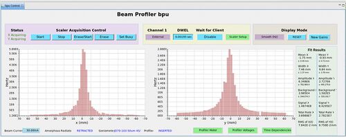
There is a beam profiler installed in the beam line just in front of the primary collimator to measure photon beam profiles. The profiler has two planes scintillator fibers to give X-Y 2D information. Each plane consists of 64 fibers of 2 mm width and they are readout by eight Hamamatsu Multi-anode PMTs.
Open Beam Profiler GUI
- Open Hall-D CSS EPICS Control if not already available following instructions.
- From Main Action Bar, click Beam Upstream Profiler in BEAM section.
- In the GUI, one will see the scaler counts plotted as a function of X and Y axes. The updating frequency is controlled by the DWEL parameter. The update interval is
DWEL×256. - There are three modes of data presentation and we are currently using two of them: Raw and Accumulative.
- The Raw mode update the plot with the new counts coming from the most recent interval.
- The Accumulative mode keeps the sum of all hits until the Reset button is pressed.
Adjust BP Voltages
The power used by the Beam Profilers includes both High Voltages and Low Voltages. The HVs are used to power the MaPMTs while the LVs are used to power the pre-amplifiers.
- High Voltage
- Each MaPMT is powered by its own HV channel. Therefore there are eight channels for each plane. These HVs can be adjusted through HV X/Y → PVU/D: Show X/Y HV Channels. As the threshold for the discriminator is embeded in hardware, adjusting the HV is the way to effectively change the threshold.
- Low Voltage
- Readouts from the same plane share two groups of Low Voltages. Each group needs two 5-V and one 1-V inputs. Always make sure that they are ON. No adjustment is allowed.
Sweeping Magnet
The sweeping magnet (DW002 dipole) in the alcove is used to clean-up the charged particles created at the collimators.
Its operational current value should be set to I=190A. This can be done using a magnet Slow Control GUI. Switch on the magnet using the magnet Slow Control GUI. Select "Input Select 1" on the main control GUI below the "Setpoint" window. Enter 190A. There is no need for hysteresis cycle.
Details about this magnet can be found here
Expert Personnel
The individuals responsible for checking that the beamlineis ready to take data and setting its operating parameters are shown in following table. Problems with normal operation of the beamline instrumentation should be referred to those individuals and any changes to their settings must be approved by them. Additional experts may be trained by the system owner and their name and date added to this table.
| Name | Component | Extension | Date of qualification |
|---|---|---|---|
| Richard Jones (UConn) | Active Collimator | (860) 377-5224 | June 4, 2014 |
| Hovanes Egiyan | BPU & GONI | x5356 | March 25, 2016 |
| Alexandre Deur | Beamline | x7526 | June 4, 2014 |
