Central Drift Chamber Shift
Contents
The Central Drift Chamber
The Central Drift Chamber (CDC) is a straw tube chamber. It has 28 layers(rings) of straws each 150cm long. It is operated with an Argon CO2 gas mixture of 50% each by mol. The nominal high voltage (HV) is +2125V and the pre-amplifier cards require low voltage (LV) drawing 0.47A of current. The gas supply is monitored and controlled by the Gas System GUI while the HV and LV are monitored and controlled by the HV GUI.
Routine Operation
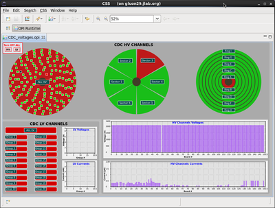
The HV GUI controls and monitors the HV and LV of the CDC. In figure 1 you see an example of the GUI with one channel off. There are three representations of the CDC status in terms of individual HV channels (left) in groups of sectors (middle) and in groups of rings(right). The color code is as follows; if the channel is off it is red as well as the sector it belongs to and the ring it belongs to. The buttons in the three CDC representations have menus to select different functions like turning on or off all channels belonging to this sector. You can also select to display a list of HV channels grouped by sector, ring or whole detector showing all parameters for the HV channels. There are two graphs for the HV and two graphs for the LV showing the voltage setting for each channel as well as the current it draws. This is a very useful visual indicator to check whether any channel is deviating from its operating parameters. During routine operation all channels should be green this will result in all three representations to be green.
Note that like all HV/LV systems the following conventions is used for the buttons. The color indicates what state a channel is in (on=green, off=red) while the text indicates the action the button will perform when pressed (off = turn channel off, on = turn channel on). This means if a channel is on the button will be green while the text will read off.
The shift worker will use the GUI to turn on and off all HV and LV as well as monitor its proper settings. If any channel is red and can not be reset with turning on/off its HV and/or LV by the shift crew the detector expert on call has to be contacted.
The gas system controls for the CDC are similar to the FDC. See either the operation of the FDC section, or the section on the Gas System.
Turning on for the first time
The detector HV and LV should be turned off when beam is established for the first time or after long periods of shutdown. Once clean beam is in the hall the detector should be turned on starting with the outer most ring. At this point you can turn on the LV for all channels. Observe the currents while the HV is ramping to the nominal values. If the ramp up was successful and the current draw on the HV channels does not cause any trips proceed to the next ring inwards. Continue this procedure till you reach the inner most ring.
Interlocks
The low voltage that powers the preamplifiers is interlocked with the air blower cooling the preamplifiers.
Pressure alarm on HD:coda:cdc:p_diff
An alarm should sound if all 3 conditions are met: (1) the DAQ is running (2) the CDC is included in the readout (3) the barometric pressure has changed by 0.1 kPa or more since the start of the run.
The ideal response from the shift crew would be to stop the run and start a new run. The alarm condition will be cleared when the new run has started.
The alarm threshold has been chosen so that the CDC's gain and time calibrations will be valid throughout the run, as we are not calibrating EVIO files singly. The alarm is set on the EPICS variable HD:coda:cdc:p_diff which watches an IOC calculating the pressure difference since the start of the run.
Running the AI for CDC gain
There is an on/off switch for the AI in the CDC HV gui. After initialization at the start of the run period this will be switched on by the AIEC team. It is no longer necessary to switch it off for the empty target runs, as RoboCDC now detects when the target is not "Full and Ready", and reverts to 2125V itself.
Extended HV alarm due to communications drop while setting HV
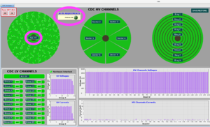
In the (rare) event that the HV is changed while one or more HV units have lost communication, the HV setpoint is changed in EPICS but the request does not reach the HV module. This results in an alarm in multiple channels (connected to the same HV supply) as the HV setpoint in EPICS no longer matches the readback HV. The alarming channel's HV gui shows this clearly - the voltage setpoint does not match the voltage setpoint readback (it is usual for the measured voltage to be up to 2V different from the setpoint, but the setpoint and setpoint readback should match). There is an example in the logbook. After checking that the IOC heartbeat is ok, then the fix for this is to use the ALL HV button (see the picture) to request the same setpoint again.
Base Line Calibration
The base line calibration program is currently set to find DAC values to level all baselines to 100 ADC counts. This script can be used for both wire chamber detectors CDC and FDC. In order to do such a calibration proceed as follows
- log into any gluon0X (X=1,2,3,4,5) computer (64 bit machines) with the account "hdcdcops"
- got to the directory /home/hdcdcops/scripts/SetDAC
- run the script ./SetAllDAC.csh [CDC,FDC]
- the option CDC or FDC will do the calibration for that particular detector only
- you can find the calibration results in the subdirectory "dacvalues"
- the calibration results will be automatically written to the ccdb_online calibration data base (CCDB_CONNECTION=mysql://ccdb_online@gluondb1/ccdb_online)
- now log has hdcdcops onto rocdev1 (32bit linux machine like all other front end rocs)
- for the correct configuration, type in: source DAQ/daq_dev_vers/work/online_setup.cshrc
- how go to /home/hdcdcops/DAQ/daq_dev_vers/daq/vme/src/rol_cdc
- there the program "mkconfigfiles" can be used to generate configuration files for each FDC and CDC roc simultaneously. Run the program like this "./mkconfigfiles -h" what kind of options you have. By default it will take the latest calibration values in the data base and set the threshold according to what is in the configuration data base table /CDC/baseline for the sparsification parameter. One can also specify the threshold as a constant value however there is a minimum value enforced that may be larger then the one you request. You can also specify the prefix name for the output file to generate unique output file names.
- options for mkconfigfiles are:
- -DAC Print Crate global settings
- -D xxxx-xx-xx select Date for data base
- -V xxxxxxxxxx select Variation for data base
- -R xxxxxxxxxx select Run Number for data base
- -S <string> set suffix for config file name
- -T threshold set constant threshold for all channels
- -H/-h this help
- the resulting configuration files have the following format: "rocDETX_fadc125_PREFIX.cnf" where DETX is (CDC1/2/3/4, FDC2/3/5/6/7/8/9/10/11/12) and _PREFIX is the files specification for identification chosen by the use. An example of such a prefix is FALL2017TH80 to indicate the fall2017 run with all thresholds set at 80 ADC counts for all channels.
- options for mkconfigfiles are:
Expert Personnel
The individuals responsible for checking that the CDC is ready to take data and setting its operating parameters are shown in following table. Problems with normal operation of the CDC should be referred to those individuals and any changes to their settings must be approved by them. Additional experts may be trained by the system owner and their name and date added to this table.
| Name | Extension | Date of qualification |
|---|---|---|
| FDC/CDC on call expert | 383-1185 | June 4, 2014 |
| Benedikt Zihlmann | 269-5310 | June 4, 2014 |

