Forward Calorimeter Expert
Contents
- 1 Intended For Expert Reference
- 1.1 FCAL Elements & Mappings
- 1.2 The Expert GUI
- 1.3 Voltage control
- 1.4 Remotely power cycle Base Power Chassis or Anagate
- 1.5 Rebooting the IOC
- 1.6 FCAL HV Scan
- 1.7 Checking Health Of Bases
- 1.8 Seeing the HV Of All Bases On A 2D Histogram
- 1.9 Finding the location of a base on the GUIs given the pvName
- 1.10 Documenting the hdfcal logbook
- 1.11 FCAL Documentation
- 1.12 FCAL LED cycling
- 1.13 FCAL Hot Checkout (HCO)
Intended For Expert Reference
More details are given here than a shift taker necessarily needs to know. An older version of the FCAL shift taker page from the commissioning era can be found here here.
FCAL Elements & Mappings
- The FCAL consists of the following elements:
- FCAL Darkroom:
- 2,800 channels, each with a lead-glass block, PMT, base, and cable to read-out electronics
- 4 sets of light, temperature, and humidity monitors
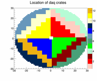
- 12 Electronics Crates
- Up to 18 fADC slots per crate
- Up to 16 channel inputs per slot, signals from FCAL
- Up to 18 fADC slots per crate
- Base communication equipment:
- 7 Anagate Quattro devices that communicate with fcal bases
- 100 bases on "strand" to each anagate x 4 strands per anagate
- 1 Anagate Uno to manage quattro devices
- 4 Power Chassis: provides power to all bases for two anagates (up to 800 bases)
- 7 Anagate Quattro devices that communicate with fcal bases
- PDU equipment:
- Expert usage only
- 1 pdu to physically power cycle Anagate devices
- 1 pdu to physically power cycle Power Chassis
- FCAL Darkroom:
The Expert GUI
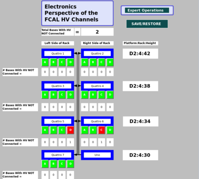
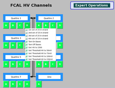
Looking at the FCAL by anagate Quattro and ports can help troubleshoot problems common to bases on a strand. The GUI shown in Figure 3 shows the 7 Quattro as they would look like on the FCAL platform. From this GUI one can enable the HV to bases on a strand or quattro level. At the moment power cycling is not integrated into EPICS so read the next section for instructions.
Mapping Base Communication/Power "Strands" to FCAL coordinates
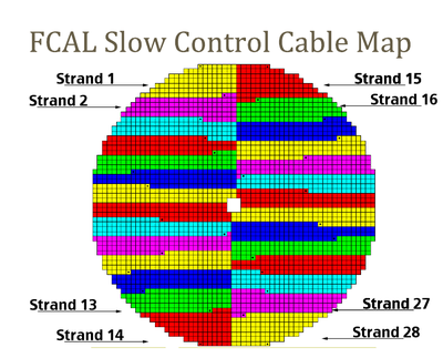
Below is slow control map where each color represents a different strand. Each strand is daisy chained to 100 bases. This view is looking upstream at the FCAL and the strands are numbered from 1 to 28. Strand 1 to 14 is only the left half of the FCAL and starts in the upper left corner and ends at the lower left corner. Strand 15 to 28 starts in the upper right corner and ends at the lower right corner.
Voltage control
The bases generate their own high voltage which can be set through the GUI interface. A non-expert user will only be able to do the following from the non-expert shift taker GUI:
- Restore HV setpoints
- Click 'SAVE/RESTORE' and select 'Restore FCAL HV Setpoints'
Note that the IOC remembers the voltage set points. During the normal cycle of getting information from the bases, the IOC will ask for the voltage set point and compare it to what is desired. If there is a difference then the IOC will update the base set point. Therefore after an Anagate or the Base Power Chassis reboot it is not necessary to restore the voltage. The only time that it is necessary to restore the voltage set points is when the IOC has been rebooted.
Remotely power cycle Base Power Chassis or Anagate
There is a Power Distribution Unit (PDU) that allows the remote power cycling of any Anagate or Base Power Chassis (BPC). This is primarily useful for resetting a base that has locked up during running. Note that sending the base reset signal, for example using the IU base software, would not clear a locked up base. Resetting the Base Power Chassis for that base is required in that case. Please turn the FCAL voltages off before power cycling the BPC so that the voltage drop that is recorded in the archiver can more easily be ignored.
To power cycle a bus do the following:
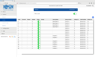
- Using any computer in Counting House open Firefox and type "fcal-basepower-pdu/" in the url, or click fcal-basepower-pdu If you can not access the pdu website from hdops, login to hdfcalops. Username "localadmin", ask experts for the password
- From left navigation menu, select "Control" and then "Loads"
- Select the outlets to power cycle and toggle the "state" switch.
- Load channel mapping:
1: base power 1
2: base power 2
3: base power 3
4: base power 4
9: anagate 1
10: anagate 2
12: anagate 4
13: anagate 5
14: anagate 6
15: anagate 7
16: anagate 3
Rebooting the IOC
If a base needs to have its HV disabled and you are unable to do so from the GUI you may need to reboot the IOC. This can be done from the "Main Action Bar"
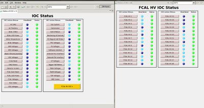
1. From any CSS GUI pull up the left navigation menu called "Main Action Bar"
2. In the "General" section area select "Status of IOCs"
3. Select the golden colored button located at the bottom right of the screen labeled "FCAL HV IOC-s"
4. Select any of the FCAL HV strands and click on "Connect to Console of IOC for FCAL HV"
5. Typing ctrl+x will crash the IOC and it will immediately try to reboot. To crash without rebooting type ctrl+t and then ctrl+x
6. If the IOC is crashed and the IOC does not reboot on its own type ctrl+t
FCAL HV Scan
The purpose of an FCAL HV scan is to determine how the signal size scales with HV for each PMT in the detector. Once the gain for a channel is determined, the HV scan can be used to find out what then new HV should be.
- Beam off
- LED cycling off (CSS, BCAL LED Pulser screen, Column pulsing script button)
- FCAL LED, blue pulsing at 200 Hz, BIAS voltage = 25 V (CSS, FCAL LED Pulser screen)
- DAQ, use configuration: EXPERT, hd_fcal.tsg and fcal_led_m9.conf
- Change the FCAL HV (CSS, FCAL Voltages, SAVE/RESTORE, Restore FCAL HV Setpoints) and choose SetTo1200Volts.snap
- take a 10k event run at each of the following HV settings: 1200 V, 1300 V, 1400 V, 1500 V, 1600 V, 1700 V, 1800 V, 1250 V, 1350 V, 1450 V, 1550 V, 1650 V, and 1750 V
- Make a log entry such as [1][2]
- The data analysis will be done by an expert
- Restore the DAQ configuration to production.
- Turn the LED cycling back on (CSS, BCAL LED Pulser screen, Column pulsing script button)
Checking Health Of Bases
Maintaining a functioning FCAL with optimal health requires collecting monitoring HV and status values for each base and finding any bases outside of some specified range. This is accomplished using the following script:
1. Login as hdops to any gluon computer
2. Go to "/gluonfs1/gluex/Subsystems/FCAL/FCAL_Analysis/scripts"
3. Type "root -l setup.C"
4. Type ".L EpicsMonitoring.C++"
5. Run the function "scan_monitoring(TString readback = ":status/:vmon", TString inequality = ">/</=", double Value = 0, bool compareSetpoint = false, bool expertLocation = false, bool nonexpertLocation = false)"
The scan_monitoring function was designed to be flexible but it does require some explanation, as given below:
First, a text file is generated with 2800 lines with the pvName in column 1 and the value in column 2, where pvName is in the form FCAL:hv:Col:Row:readback. The text file is then parsed and compared to "Value" yielding a true/false condition depending on "inequality". pvNames that pass this condition are printed to the screen.
The parameter "compareSetpoint" will compare the measured HV with the set HV and if the absolute difference is greater that the parameter "Value" then it is printed to the screen. These are the only parameters that matter in this case.
Besides the pvNames you may also want to navigate the GUIs to find that base. For an expert the location would be Anagate Quattro Number : Port : Position in strand. For a nonexpert the location would be Quadrant : Strand : Position in strand. These options can be set by setting either or both "expertLocation" or "nonexpertLocation" to true.
Readback can take any suffix used by epics to tag the type of base response. The list of possible variables monitored by epics are:
- :v0set = this is NOT a variable that comes from the base BUT a something you can set in epics and is reset to 0 every time the IOC reboots
- :status = is 0 or 1 depending if the base is disabled or enabled, respectively
- :vmon = measured HV
- :imon = measured Current
- :dyn = measured Dynode HV
- :dac = Digital Analog Converter used by the base to set a HV
- :mvb = The average voltage supplied to the bottom half of pins is called Medium Voltage Bottom
- :mvt = The average voltage supplied to the top half of pins is called Medium Voltage Top
Examples:
1. To find all bases whose HV is disabled do type the following:
scan_monitoring(":status","=",0,false)
2. To find all bases whose measured HV is greater than 2000 Volts do the following:
scan_monitoring(":vmon",">",2000,false)
3. To find all bases where the absolute difference between the measured and set HV is greater than 300 do the following: (The readback and inequality parameter are irrelevant when "compareSetpoint" is true)
scan_monitoring("","",300,true)
Seeing the HV Of All Bases On A 2D Histogram
To see the HV values for all channels do the following:
1. Login as hdops to any gluon computer
2. Go to "/gluonfs1/gluex/Subsystems/FCAL/FCAL_Analysis/scripts"
3. Type "root -l setup.C"
4. Type ".L EpicsMonitoring.C++"
5. Run plot_voltages_2d(true)
Finding the location of a base on the GUIs given the pvName
The pvName is in the form "FCAL:hv:Col:Row". To find this base on the GUI and display it in the table you need either the Quadrant or Anagate Number, the Port or Strand, and the Position in the strand. This can be done by executing the script "EpicsMonitoring.C" as explained in the previous section. The functions are:
- expertName(string pv) which outputs a string in the form Anagate Quattro Number : Port Letter : Position in strand
- nonexpertName(string pv) which outputs a string in the form Quadrant : Strand : Position in strand
Documenting the hdfcal logbook
Keeping track of bases that have their HV disabled or are not setting a correct HV is important and will be updated on a daily basis. This will be done using the logbook and should be organized as follows:
1. Got to logbooks.jlab.org/book/hdfcal and login
2. Click the "Add Content" link on the top right
3. Set the "Title" area to "Daily FCAL Health"
4. In the body there will be two sections
- Section 1: HV Disbaled
- Underneath this section title list the problem bases by their pv names (FCAL:hv:Col:Row) and a comment explaining why it's disabled
- Section 2: Absolute difference between measured HV and setpoint HV is greater than 1000 Volts
- Underneath this section title list the problem bases by their pv names (FCAL:hv:Col:Row) and a comment explaining why the absolute difference is so large
FCAL Documentation
[The FCAL CAN Bus, Claire Tarbert] FCAL Manual, Manuel Lara FCAL Base Manual, Jonathan Zarling
FCAL LED cycling
For the non-expert, the pulsing mechanism can be turned on and off using the button that is located on the BCAL Pulser screen. In the future, a dedicated button will be added to the FCAL screen but this is not available yet.
During production running the FCAL LEDs are cycled through 6 configurations, each 1 minute long and tied to the wall clock.
The previous configuration had 10 minutes long periods, as follows. (This is old and stopped in March 2022.)
Violet 12 V    (00 to 09 minutes)
Blue   10 V    (10 to 19 minutes)
Green  29 V    (20 to 29 minutes)
Violet 22 V    (30 to 39 minutes)
Blue   15 V    (40 to 49 minutes)
No pulsing     (50 to 59 minutes)
This is accomplished using the following script which is run as hdops on gluon27
 ssh hdops@gluon27
 cd /home/hdops/hd_utilities/FCAL_Scripts/
 runPulser_3LED_5cycle.py
A cron job is run as hdops on gluon27 to monitor that this script is running
crontab -e
*/10 * * * * /home/hdops/hd_utilities/FCAL_Scripts/cron_fcal_pulser.csh > /dev/null
