Difference between revisions of "Forward Calorimeter Shift"
(→FCAL Base lockup) |
|||
| (107 intermediate revisions by 5 users not shown) | |||
| Line 1: | Line 1: | ||
| − | = | + | = Forward Calorimeter Summary = |
| − | + | ||
| − | + | [[Image:FCAL_construction.JPG | thumb |left| 300px | Fig. 1. FCAL during construction, view looking downstream]] | |
| − | [[Image: | + | |
| − | + | ||
| − | + | ||
| − | + | ||
| − | + | ||
| − | + | ||
| − | + | ||
| − | + | The hall D Forward Calorimeter (FCAL) is an electromagnetic calorimeter designed to detect neutrals in the forward direction from approximately 2-11 degrees in lab theta, measuring from the center of the target. | |
| − | + | ||
| − | + | ||
| − | + | ||
| − | + | ||
| − | + | The Forward Calorimeter is a 2800 element lead glass detector consisting of 4cm x 4cm x 45cm bars. The light produced in each element is measured using FEU 84-3 PMTs. The PMTs are powered using custom Cockcroft-Walton bases and operate up to 1800 V. The entire detector exists inside an environmentally controlled and light-tight "darkroom" on the FCAL platform. Individual PMTs respond differently to a fixed voltage, so each channel has an independent voltage setting determined from a gain balancing procedure. | |
| − | + | ||
| − | + | ||
| − | + | ||
| − | + | ||
| − | + | The FCAL expert page can be found [https://halldweb.jlab.org/hdops/wiki/index.php/Forward_Calorimeter_Expert here]. It contain more detailed information if you want a more detailed description of FCAL elements and operation. | |
| − | [ | + | |
| − | + | ||
| − | + | ||
| − | |||
| − | + | =Interlocks= | |
| − | 2. | + | [[Image:FCAL_darkroom.PNG | thumb | right| 400px | Fig. 2. FCAL Darkroom GUI page]] |
| − | + | A set of "interlocks" monitor the status inside the darkroom and are set to shut off power to bases and PMTs should these exceed set limits. This is mostly done to protect PMTs from potential damage from too much ambient light. There are sensors for the darkroom double doors and four sensor boxes in the darkroom. Each sensor box monitors temperature, humidity, and light levels. | |
| − | + | Power supplies for the bases are interlocked and will be turned off when any of the following occurs: | |
| + | # both doors to the dark room are open simultaneously, | ||
| + | # environmental sensors (light, temperature or humidity) in the dark room exceed preset limits or | ||
| + | # there is a loss of power. | ||
| − | + | Should the interlock system trip, an expert should be called to reset the condition. Changes to the interlock settings are only allowed by an expert, or under his/her guidance. | |
| + | = Routine operation= | ||
| + | ==FCAL Occupancies== | ||
| + | FCAL occupancies will likely have a small number of features to them. Isolated channels may have no/low occupancy (or more rarely very high occupancy). This may vary run-to-run a little bit. This type of behavior doesn't require notifying FCAL experts. | ||
| − | + | Any behavior other than the above should be reported to FCAL experts. A typical occupancy plot from Spring '17 is shown here: | |
| + | [[Image:Fcal_digOcc2D.png|thumb|center|500px]] | ||
| − | + | ==FCAL EPICS GUI Screens== | |
| + | * '''FCAL Voltages''': This screen gives information on FCAL bases providing power to PMTs. This gives an overview of the FCAL HV status, can be used to power channels on/off, and to navigate to individual channels. <font color=red>Red </font> channels have been turned off by FCAL experts. <font color=yellow>Yellow</font> channels indicate either voltage or communication issues. Problematic channels will most likely line up with holes in occupancy. | ||
| + | *'''FCAL Darkroom''': This gives an overview of sensors monitoring the environment inside the FCAL darkroom. These should always be green unless someone is inside the darkroom. | ||
| + | *'''FCAL LED pulser''': The long and short term behavior of the FCAL is monitored by an LED pulser and controlled here. This should always be running at 10 Hz and cycles between three different colors hourly. If no LED pulser appears to be going, contact an FCAL expert. Do not change anything here unless you know what you are doing! | ||
| + | *'''FCAL Scalars''': This gives fADC scalar readouts from the FCAL for individual channels. | ||
| − | + | ==FCAL Alarms== | |
| − | + | ||
| − | === | + | ===Dark room=== |
| − | + | ||
| − | + | ||
| − | + | ||
| − | + | Potential FCAL alarms could come from environmental monitors inside the FCAL darkroom. However, it is not expected that we should ever reach any alarm values. The FCAL Darkroom environmental variables can be viewed using MyaViewer and selecting the group 'HD_FCAL_ROOM' | |
| − | + | ||
| − | The | + | |
| − | + | ||
| − | + | ||
| − | + | ||
| − | Below is a brief explanation of the other functionality capable on the non-expert GUI, but a shift taker must be directed by an expert to use any of the following: | + | ===High Voltage=== |
| + | |||
| + | * Problems with the FCAL voltage on a base will be indicated by a yellow box around a channel on the the FCAL voltage GUI. | ||
| + | * These are diagnosed by clicking on the channel to bring up the '''Single Channel''' screen. | ||
| + | *# If the ''Voltage Setpoint'' and the ''Voltage Setpoint Readback'' are similar but the ''Measured Voltage'' is near to 0, this can be corrected as follows: | ||
| + | *## On the channel with issues begin lowering the voltage by clicking on the ''Voltage Setpoint'' arrows. After about 20 V of change the ''Measured Voltage'' should jump to the correct value. | ||
| + | *## Do this for all channels with issues. | ||
| + | *## Restore the voltages using the "SAVE/RESTORE" button on the voltage GUI to fix your changes. | ||
| + | |||
| + | Below is a brief explanation of the other functionality capable on the non-expert GUI, <font color=red>but a shift taker must be directed by an expert to use any of the following</font>: | ||
* Enable HV on all bases | * Enable HV on all bases | ||
** Click 'All FCAL HV' and select 'Turn On All Bases' | ** Click 'All FCAL HV' and select 'Turn On All Bases' | ||
* Disable the HV on all bases | * Disable the HV on all bases | ||
| − | ** Can be done in 2 ways: | + | ** Can be done in 2 ways: |
| + | **# At the top of the screen there is a red outline area with 'Turn OFF ALL' written, click the 'HV' button to power off all bases, | ||
| + | **# click 'All FCAL HV' and select 'Turn Off All Bases' | ||
* Save HV setpoints | * Save HV setpoints | ||
** Click 'SAVE/RESTORE' and select 'Save FCAL HV Setpoints' | ** Click 'SAVE/RESTORE' and select 'Save FCAL HV Setpoints' | ||
| − | |||
| − | |||
| − | === | + | ==FCAL Base lockup== |
| − | + | ||
| − | + | Bases might lose communication and stop providing high voltage. This is identified when the '''channel GUI (click on the channel in the voltage GUI) shows the alarm state as "INVALID, LINK ALARM"''' when the mouse is hovered over the yellow Chanel Status indicator. If this instead shows "OK, OK" then the base is not locked up. | |
| − | + | In addition | |
| − | + | # the voltage GUI has a yellow border for the channel indicating alarm | |
| + | # The scalers show zero counts for the channel (the RootSpy occupancy may also show a hole.) | ||
| + | This is corrected by the following sequence: | ||
| + | # End the run. We usually don't end a run early for this issue. | ||
| + | # Turn off the high voltage to the whole FCAL. | ||
| + | # Run the script. "/home/hdops/FCAL/tools/FCAL_basePowerReset.py" | ||
| + | # Wait for 30 seconds. | ||
| + | # Turn on the FCAL high voltage. | ||
| + | # Start a new run (as appropriate). | ||
| + | # '''MAKE A LOG ENTRY with the number of the locked up base.''' | ||
| + | <gallery mode="packed" widths=300px heights=350px> | ||
| + | File:base_lockup_V.png|Figure: FCAL voltage showing 2 alarm channels | ||
| + | File:base_lockup_scalers.png|Figure: FCAL scalers showing 2 missing channels | ||
| + | File:base_lockup_channel.png|Figure: FCAL channel showing a communication failure alarm | ||
| + | File:base_lockup_RootSpy.png|Figure: FCAL occupancy in RootSpy showing 2 missing channels | ||
| + | </gallery> | ||
| − | + | =Expert personnel = | |
| − | + | ||
| − | + | ||
| − | + | ||
| − | + | ||
| − | + | ||
| − | + | ||
| − | + | ||
| − | + | ||
| − | + | ||
The individuals responsible for checking that the FCAL is ready to take data and setting its operating parameters are shown in following table. | The individuals responsible for checking that the FCAL is ready to take data and setting its operating parameters are shown in following table. | ||
Problems with normal operation of the FCAL should be referred to those individuals and any changes to their settings must be | Problems with normal operation of the FCAL should be referred to those individuals and any changes to their settings must be | ||
| Line 98: | Line 94: | ||
! width=200px | Name !! width=100px | Number !! Date of qualification | ! width=200px | Name !! width=100px | Number !! Date of qualification | ||
|- | |- | ||
| − | | | + | | Calorimeter Expert || align=center | 354-9399 || align=center| |
| + | |- | ||
| + | | Mark Dalton || align=center | Cell:757-849-2929 || align=center | | ||
| + | |- | ||
| + | | Malte Albrecht || align=center | Cell:757-316-4936 || align=center | | ||
|} | |} | ||
Latest revision as of 09:03, 23 January 2023
Contents
Forward Calorimeter Summary

The hall D Forward Calorimeter (FCAL) is an electromagnetic calorimeter designed to detect neutrals in the forward direction from approximately 2-11 degrees in lab theta, measuring from the center of the target.
The Forward Calorimeter is a 2800 element lead glass detector consisting of 4cm x 4cm x 45cm bars. The light produced in each element is measured using FEU 84-3 PMTs. The PMTs are powered using custom Cockcroft-Walton bases and operate up to 1800 V. The entire detector exists inside an environmentally controlled and light-tight "darkroom" on the FCAL platform. Individual PMTs respond differently to a fixed voltage, so each channel has an independent voltage setting determined from a gain balancing procedure.
The FCAL expert page can be found here. It contain more detailed information if you want a more detailed description of FCAL elements and operation.
Interlocks

A set of "interlocks" monitor the status inside the darkroom and are set to shut off power to bases and PMTs should these exceed set limits. This is mostly done to protect PMTs from potential damage from too much ambient light. There are sensors for the darkroom double doors and four sensor boxes in the darkroom. Each sensor box monitors temperature, humidity, and light levels.
Power supplies for the bases are interlocked and will be turned off when any of the following occurs:
- both doors to the dark room are open simultaneously,
- environmental sensors (light, temperature or humidity) in the dark room exceed preset limits or
- there is a loss of power.
Should the interlock system trip, an expert should be called to reset the condition. Changes to the interlock settings are only allowed by an expert, or under his/her guidance.
Routine operation
FCAL Occupancies
FCAL occupancies will likely have a small number of features to them. Isolated channels may have no/low occupancy (or more rarely very high occupancy). This may vary run-to-run a little bit. This type of behavior doesn't require notifying FCAL experts.
Any behavior other than the above should be reported to FCAL experts. A typical occupancy plot from Spring '17 is shown here:

FCAL EPICS GUI Screens
- FCAL Voltages: This screen gives information on FCAL bases providing power to PMTs. This gives an overview of the FCAL HV status, can be used to power channels on/off, and to navigate to individual channels. Red channels have been turned off by FCAL experts. Yellow channels indicate either voltage or communication issues. Problematic channels will most likely line up with holes in occupancy.
- FCAL Darkroom: This gives an overview of sensors monitoring the environment inside the FCAL darkroom. These should always be green unless someone is inside the darkroom.
- FCAL LED pulser: The long and short term behavior of the FCAL is monitored by an LED pulser and controlled here. This should always be running at 10 Hz and cycles between three different colors hourly. If no LED pulser appears to be going, contact an FCAL expert. Do not change anything here unless you know what you are doing!
- FCAL Scalars: This gives fADC scalar readouts from the FCAL for individual channels.
FCAL Alarms
Dark room
Potential FCAL alarms could come from environmental monitors inside the FCAL darkroom. However, it is not expected that we should ever reach any alarm values. The FCAL Darkroom environmental variables can be viewed using MyaViewer and selecting the group 'HD_FCAL_ROOM'
High Voltage
- Problems with the FCAL voltage on a base will be indicated by a yellow box around a channel on the the FCAL voltage GUI.
- These are diagnosed by clicking on the channel to bring up the Single Channel screen.
- If the Voltage Setpoint and the Voltage Setpoint Readback are similar but the Measured Voltage is near to 0, this can be corrected as follows:
- On the channel with issues begin lowering the voltage by clicking on the Voltage Setpoint arrows. After about 20 V of change the Measured Voltage should jump to the correct value.
- Do this for all channels with issues.
- Restore the voltages using the "SAVE/RESTORE" button on the voltage GUI to fix your changes.
- If the Voltage Setpoint and the Voltage Setpoint Readback are similar but the Measured Voltage is near to 0, this can be corrected as follows:
Below is a brief explanation of the other functionality capable on the non-expert GUI, but a shift taker must be directed by an expert to use any of the following:
- Enable HV on all bases
- Click 'All FCAL HV' and select 'Turn On All Bases'
- Disable the HV on all bases
- Can be done in 2 ways:
- At the top of the screen there is a red outline area with 'Turn OFF ALL' written, click the 'HV' button to power off all bases,
- click 'All FCAL HV' and select 'Turn Off All Bases'
- Can be done in 2 ways:
- Save HV setpoints
- Click 'SAVE/RESTORE' and select 'Save FCAL HV Setpoints'
FCAL Base lockup
Bases might lose communication and stop providing high voltage. This is identified when the channel GUI (click on the channel in the voltage GUI) shows the alarm state as "INVALID, LINK ALARM" when the mouse is hovered over the yellow Chanel Status indicator. If this instead shows "OK, OK" then the base is not locked up.
In addition
- the voltage GUI has a yellow border for the channel indicating alarm
- The scalers show zero counts for the channel (the RootSpy occupancy may also show a hole.)
This is corrected by the following sequence:
- End the run. We usually don't end a run early for this issue.
- Turn off the high voltage to the whole FCAL.
- Run the script. "/home/hdops/FCAL/tools/FCAL_basePowerReset.py"
- Wait for 30 seconds.
- Turn on the FCAL high voltage.
- Start a new run (as appropriate).
- MAKE A LOG ENTRY with the number of the locked up base.
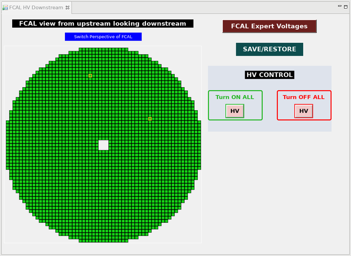
Figure: FCAL voltage showing 2 alarm channels
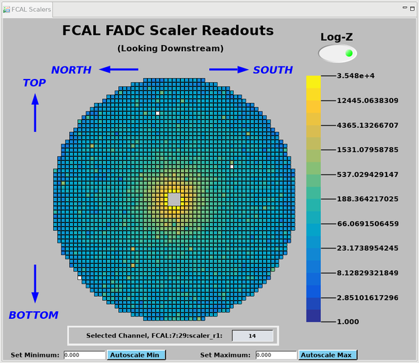
Figure: FCAL scalers showing 2 missing channels
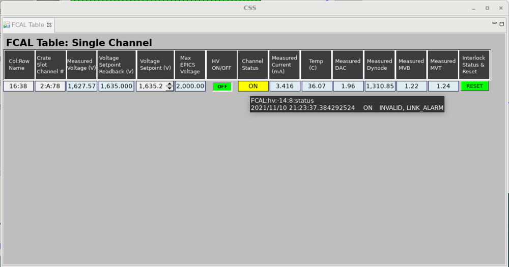
Figure: FCAL channel showing a communication failure alarm
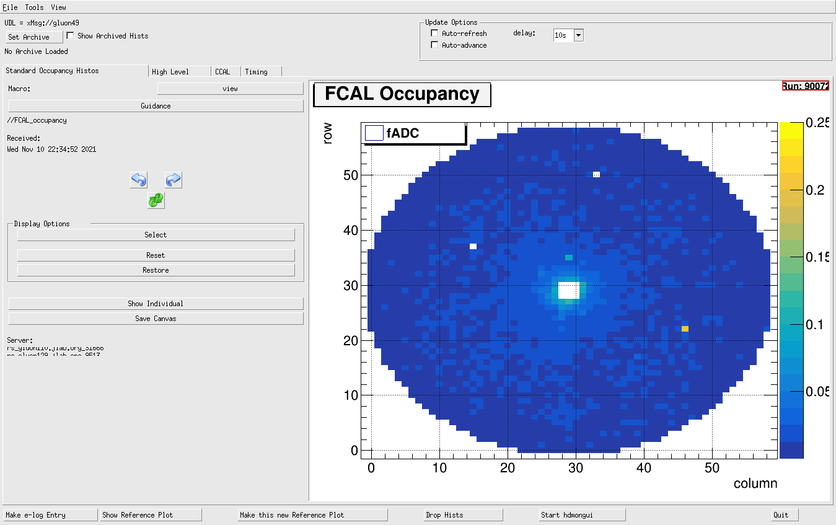
Figure: FCAL occupancy in RootSpy showing 2 missing channels


Expert personnel
The individuals responsible for checking that the FCAL is ready to take data and setting its operating parameters are shown in following table. Problems with normal operation of the FCAL should be referred to those individuals and any changes to their settings must be approved by them. Additional experts may be trained by the system owner and their name and date added to this table.
| Name | Number | Date of qualification |
|---|---|---|
| Calorimeter Expert | 354-9399 | |
| Mark Dalton | Cell:757-849-2929 | |
| Malte Albrecht | Cell:757-316-4936 |