Difference between revisions of "Plan for mapping PS magnet"
From GlueXWiki
m (Text replacement - "/halldweb1.jlab.org/" to "/halldweb.jlab.org/") |
|||
| (13 intermediate revisions by one other user not shown) | |||
| Line 6: | Line 6: | ||
[[image:18d36_satur.png|550px]] | [[image:18d36_satur.png|550px]] | ||
| + | |||
| + | |||
| + | [https://halldweb.jlab.org/beamline TOSCA simulation results] | ||
| Line 28: | Line 31: | ||
(1st measure fringe field for the maximum Z range allowed by the mapper) | (1st measure fringe field for the maximum Z range allowed by the mapper) | ||
| − | * - | + | * -22 cm < X < 22 cm |
* Z = -1 cm, 0 cm, 1 cm, (3 cm) | * Z = -1 cm, 0 cm, 1 cm, (3 cm) | ||
| + | |||
'' Upstream end of the magnet '' | '' Upstream end of the magnet '' | ||
| Line 38: | Line 42: | ||
* -5 cm < X < 5 cm | * -5 cm < X < 5 cm | ||
| − | * | + | * Y = -1 cm, 0 cm, 1 cm, (3 cm) |
''' Step size ''' | ''' Step size ''' | ||
* 1 cm in X and Z | * 1 cm in X and Z | ||
| − | |||
| Line 55: | Line 58: | ||
* ( 1 T) | * ( 1 T) | ||
| + | |||
| + | |||
| + | ''' Mapping procedure ''' | ||
| + | |||
| + | * Map the fild along the beamline for B = 1.8 T (Y = 0) and compare with TOSCA | ||
| + | |||
| + | * Make a 2-D map for various fields: B = 1.8 T, 1.9 T, 1.5 T (1 T?) | ||
| + | |||
| + | * Make a 2-D map for B = 1.8 T at Y = -1 cm and 1 cm. We'll decide whether a 3D map is needed for other fields when we get data | ||
| + | |||
| + | |||
| + | * Can we rotate 2 Hall probes to measure Bz and Bx ? | ||
Latest revision as of 03:25, 1 April 2015
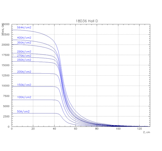
TOSCA simulation provided by S. Glamazdin. Field profile along the Z axis. Z = 0 cm is at the center of the magnet.
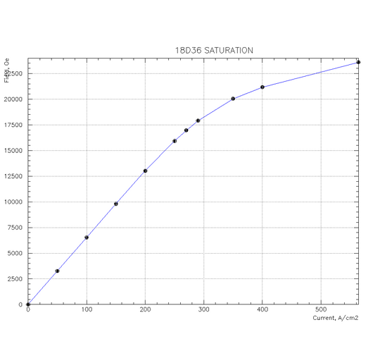
Saturation
Mapping Requirements
Coordinate system
- The origin (0,0,0) is the geometric center of the magnetic poles, located in the middle of the gap.
- Z axis is along the beam and points along the photon beam direction
- Y is vertical
- X is perpendicular to the beam points to the Hall D south wall
Mapping Regions
Downstream end of the magnet
- 0 cm < Z < 90 cm
(1st measure fringe field for the maximum Z range allowed by the mapper)
- -22 cm < X < 22 cm
- Z = -1 cm, 0 cm, 1 cm, (3 cm)
Upstream end of the magnet
- -90 cm < Z < 0 cm
- -5 cm < X < 5 cm
- Y = -1 cm, 0 cm, 1 cm, (3 cm)
Step size
- 1 cm in X and Z
Mapping Fields
- 1.8 T
- 1.9 T
- 1.5 T
- ( 1 T)
Mapping procedure
- Map the fild along the beamline for B = 1.8 T (Y = 0) and compare with TOSCA
- Make a 2-D map for various fields: B = 1.8 T, 1.9 T, 1.5 T (1 T?)
- Make a 2-D map for B = 1.8 T at Y = -1 cm and 1 cm. We'll decide whether a 3D map is needed for other fields when we get data
- Can we rotate 2 Hall probes to measure Bz and Bx ?

