Difference between revisions of "BCAL Monitoring"
From GlueXWiki
(→Photos and Plots) |
(→Photos and Plots) |
||
| Line 15: | Line 15: | ||
# Jig to place LED string for gluing side view perspective [[Media:LED_glue2.JPG]] | # Jig to place LED string for gluing side view perspective [[Media:LED_glue2.JPG]] | ||
# Jig to place LED string for gluing / remaining glue after gluing and removal [[Media:LED_glue3.JPG]] | # Jig to place LED string for gluing / remaining glue after gluing and removal [[Media:LED_glue3.JPG]] | ||
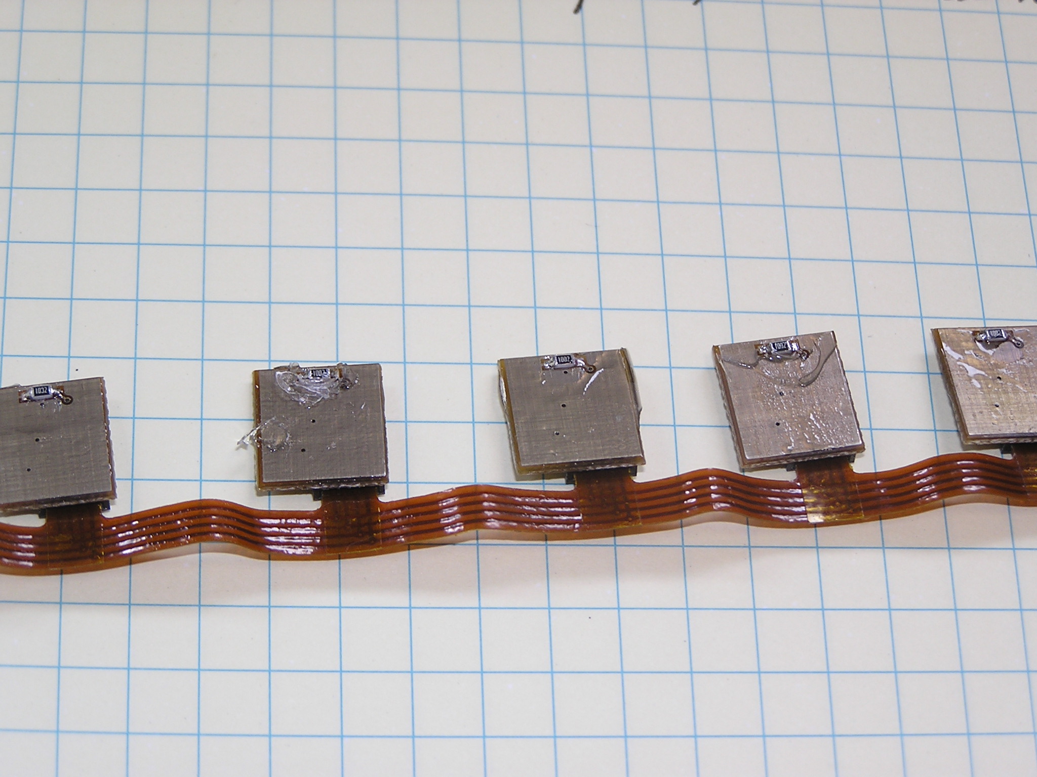
| + | # LEDs located on the front face of third row from bottom (T3) to simulate illumination from the light guide input [[Media:PF1010003.JPG]] | ||
Revision as of 17:49, 12 October 2012
Photos and Plots
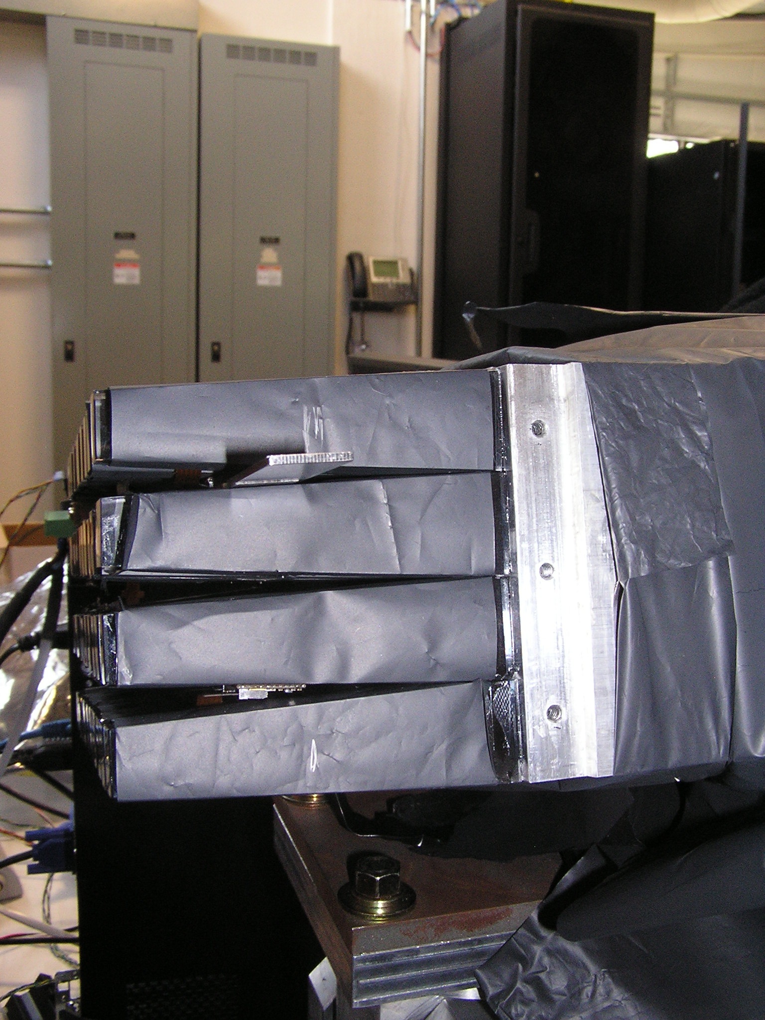
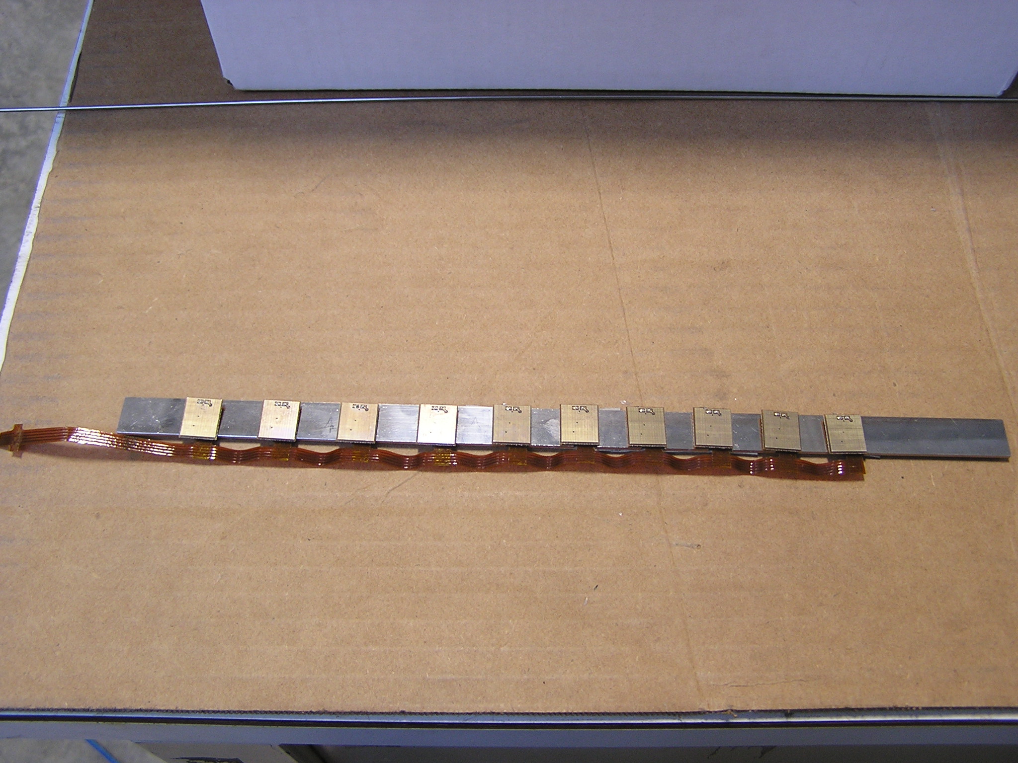
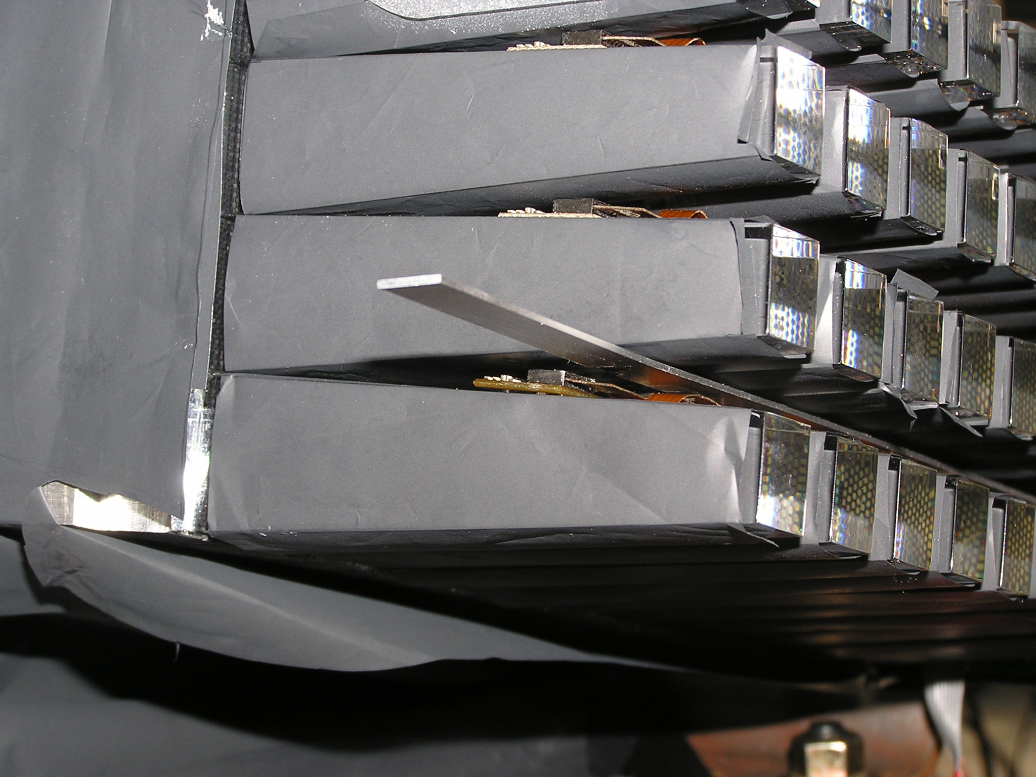
- Overview of LED string and support between light guides Media:BCAL_LED_overview.JPG
- All LEDs on. Maximum depth of arrangement into light guides Media:BCAL_monitoring_stuck.JPG
- Last LED off. Support reached depth of hole Media:BCAL_monitoring_NoLED.JPG
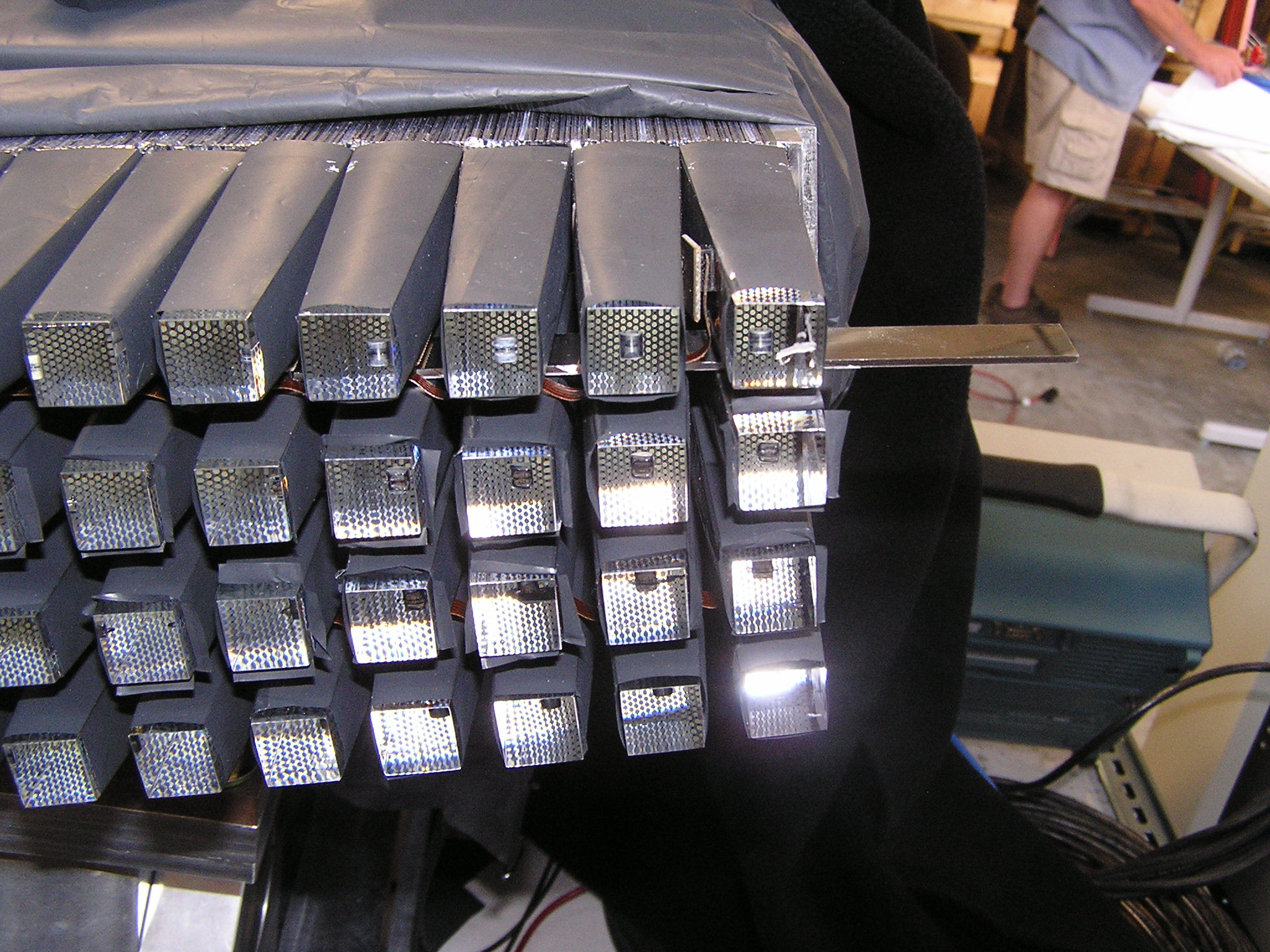
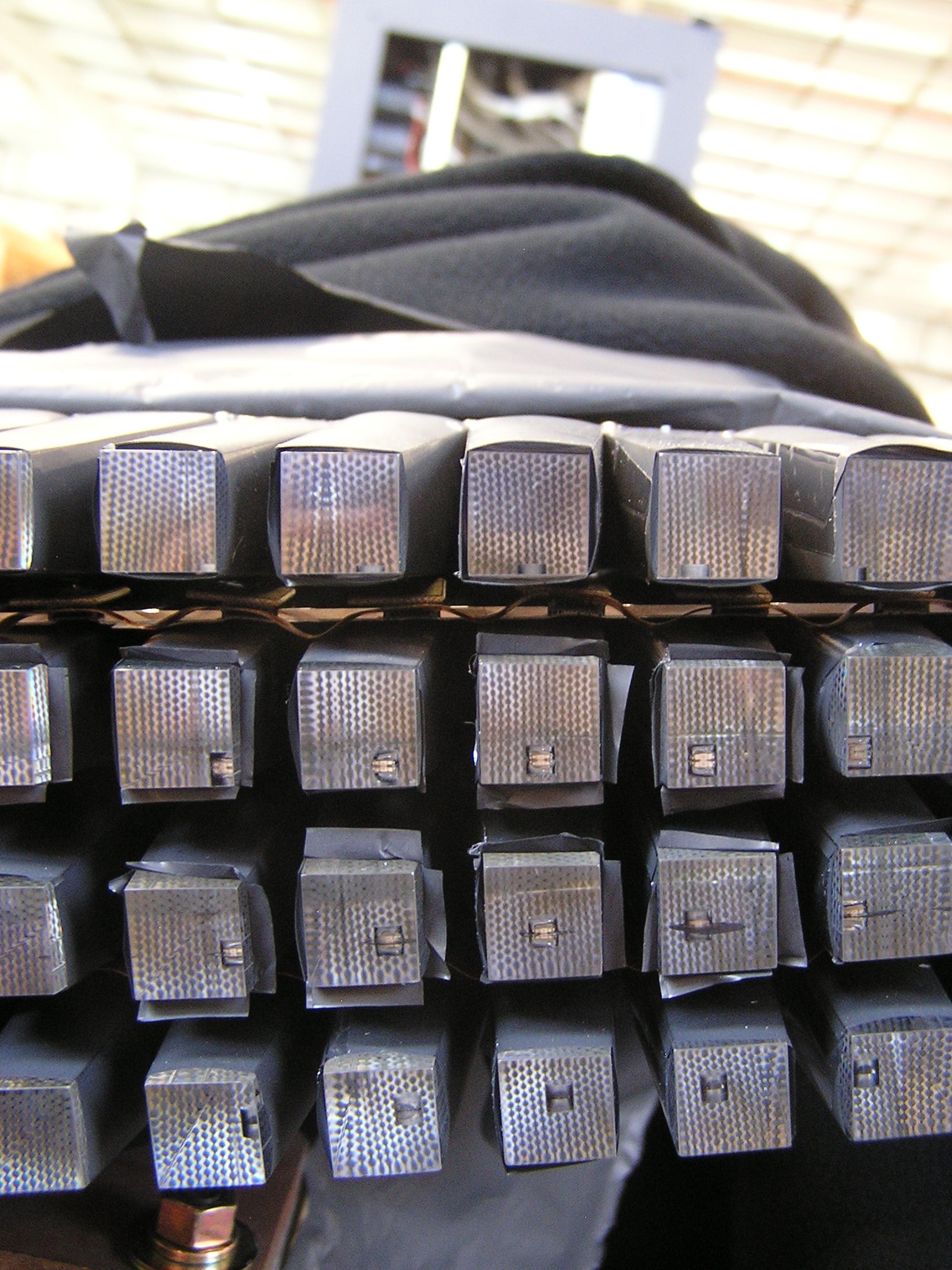
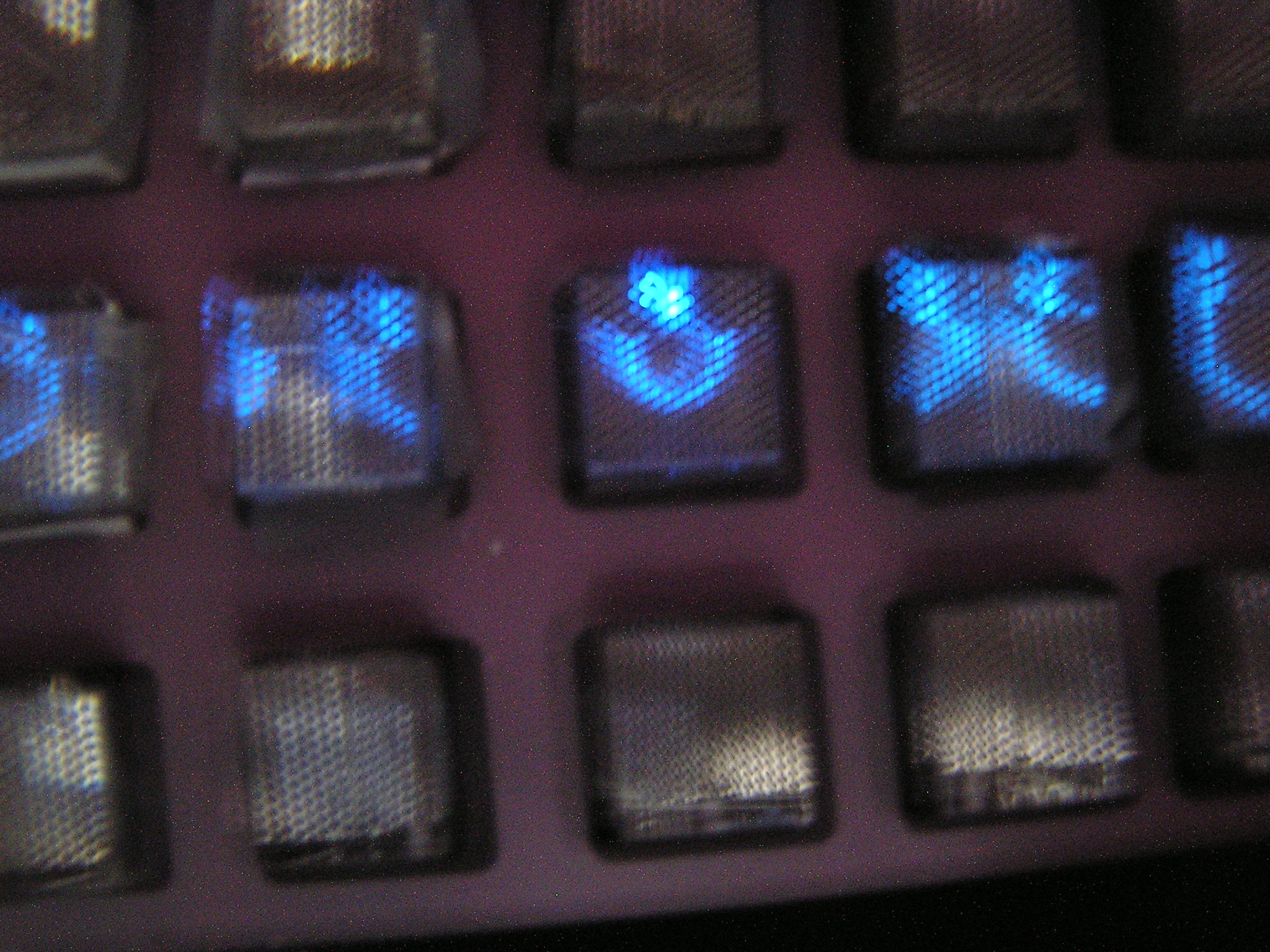
- End view of light guides, showing holes with LEDs and holes without Media:BCAL_monitoring_LEDs.JPG
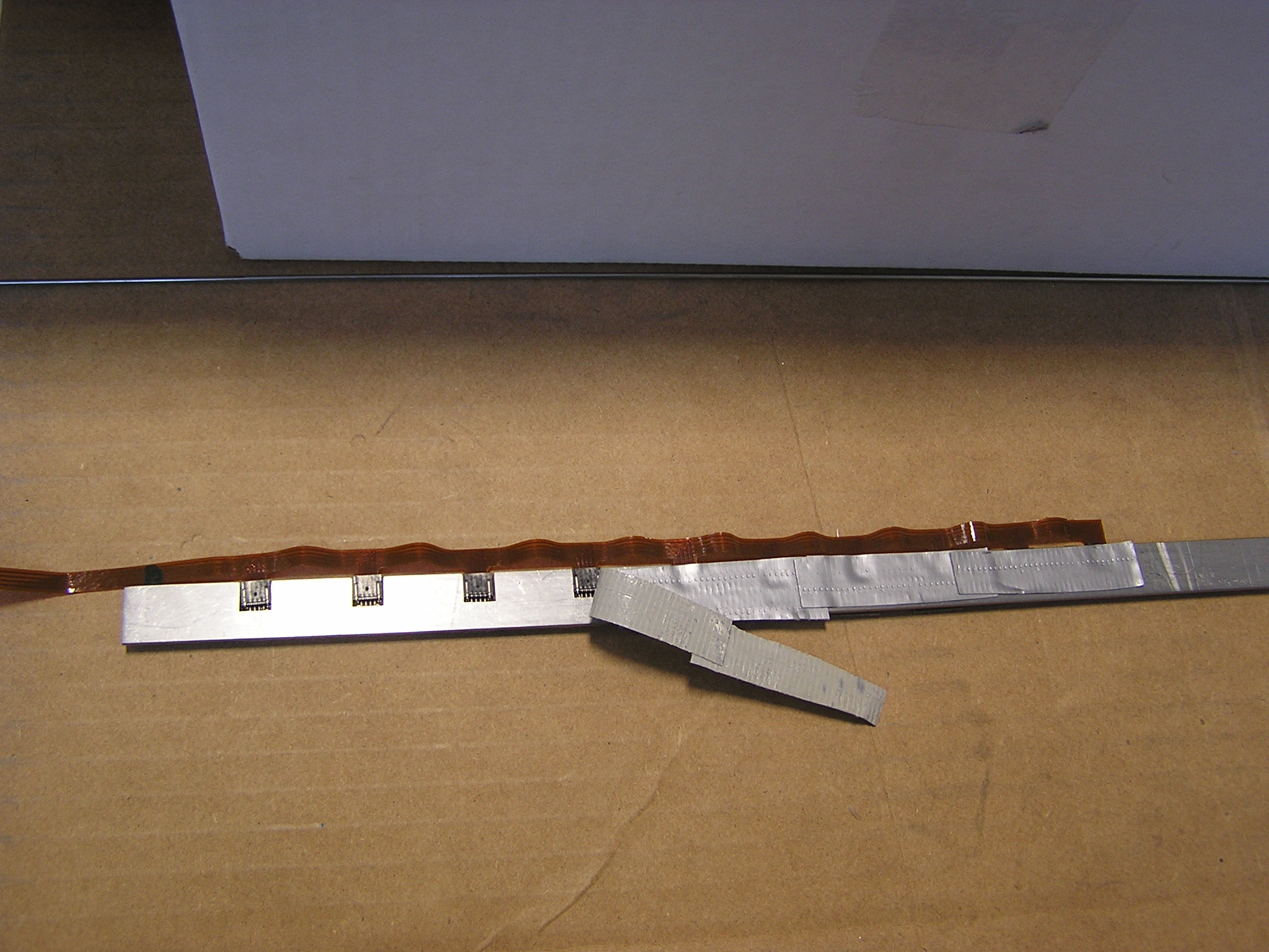
- Initial version of support to hole LEDs during installation Media:BCAL monitoring supports.JPG
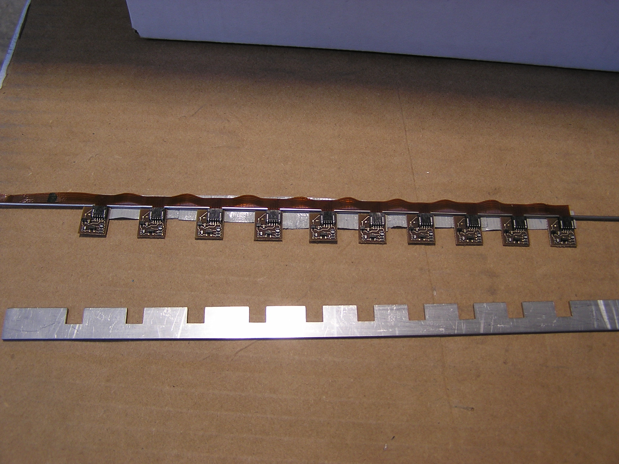
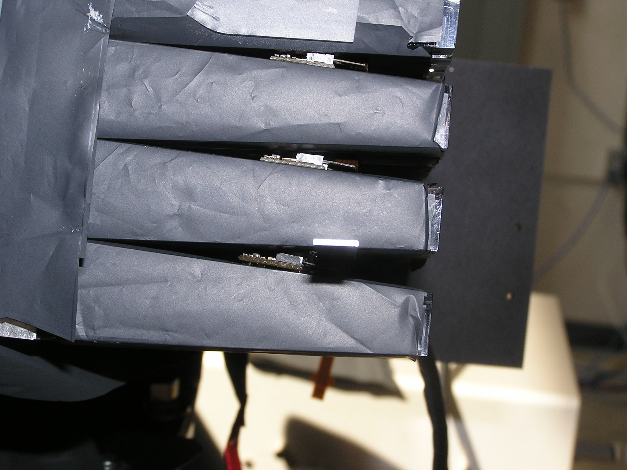
- View of LED boards on support. Up side faces light guide and hole Media:BCAL_monitoring_insideview.JPG
- View of LED boards on support. Up side faces away from light guide and hole. Tape holds boards during installation Media:LED monitoring outsideview.JPG
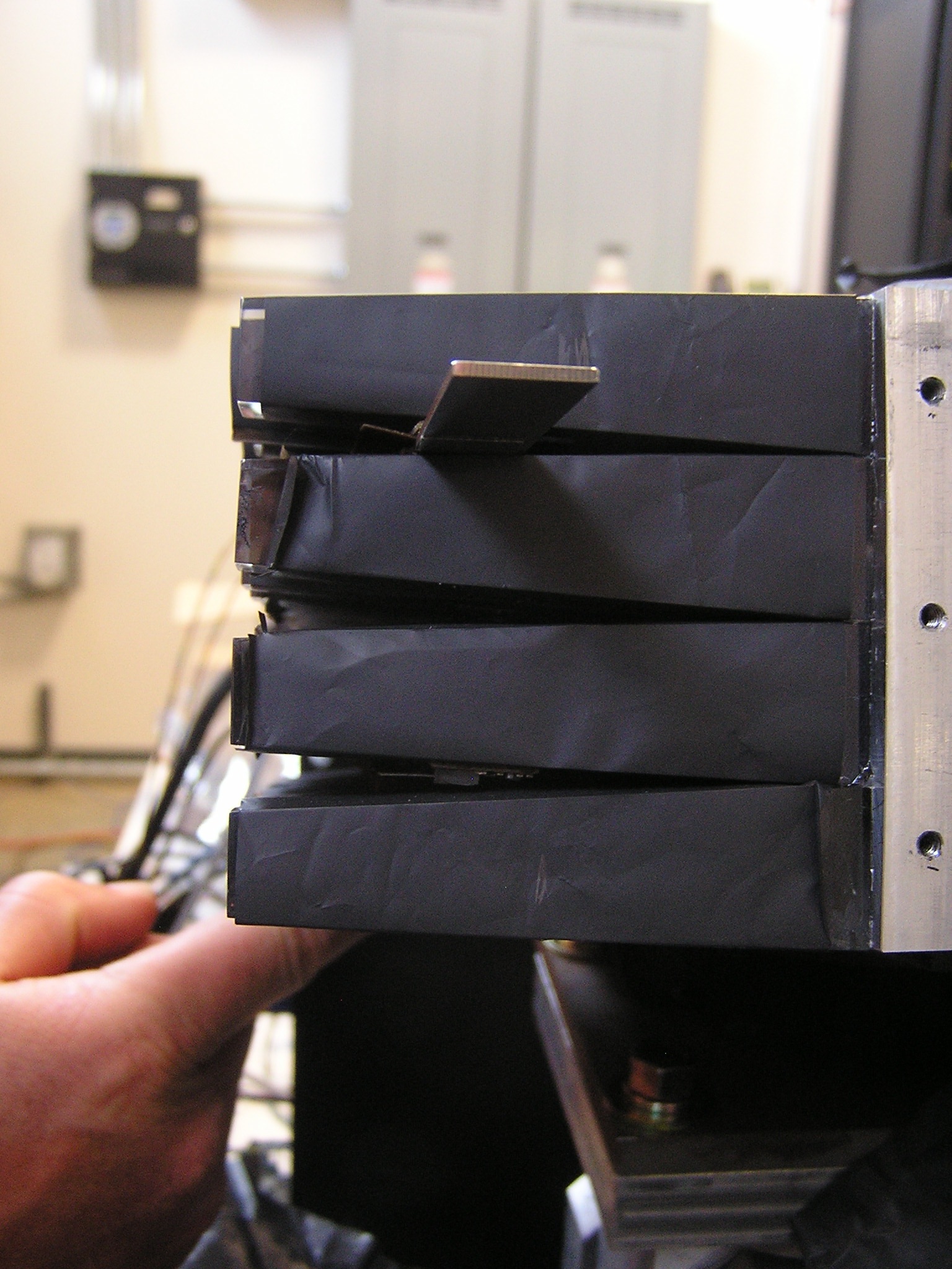
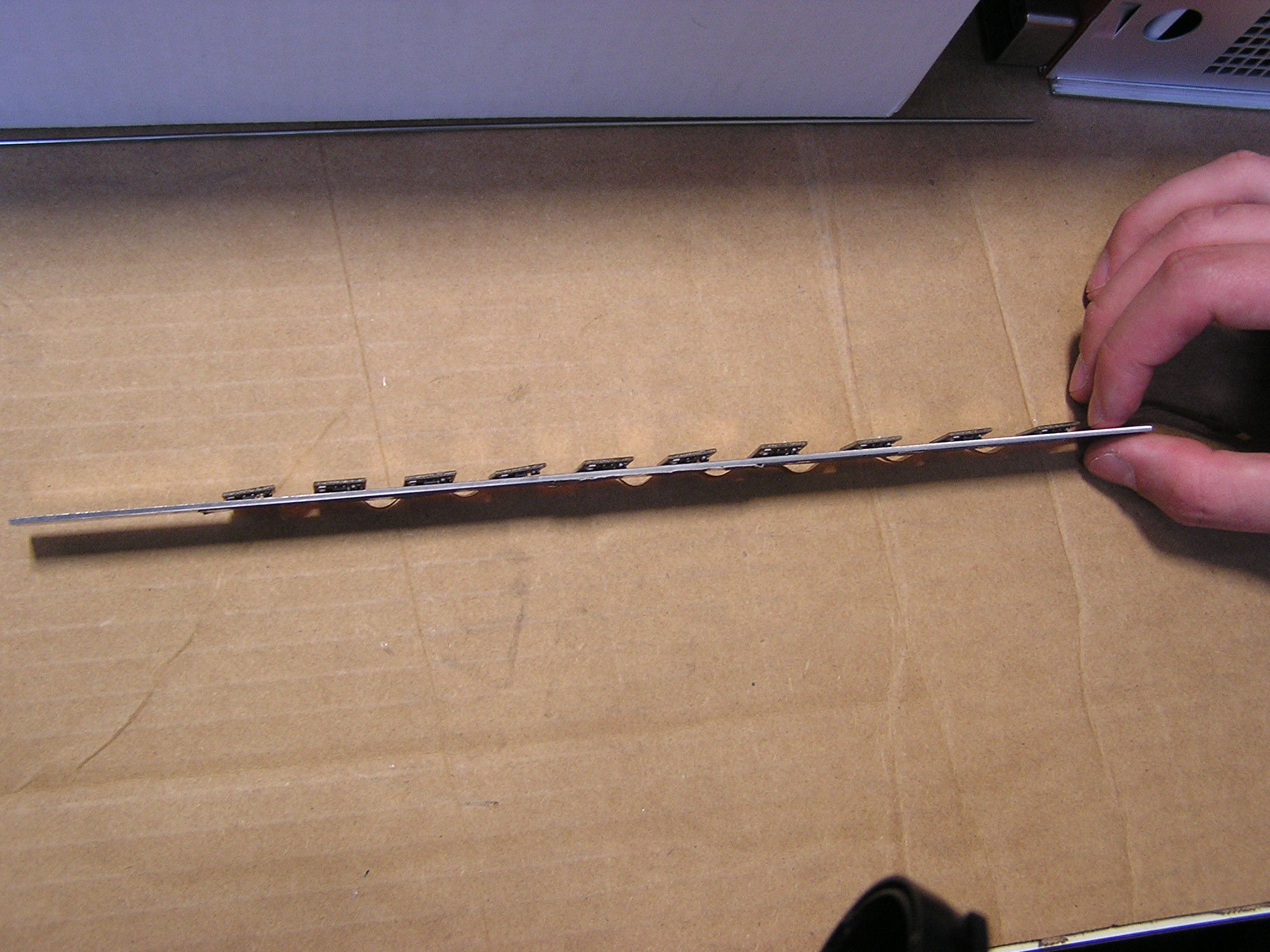
- View of LED boards on support. End view to show thickness of initial version Media:BCAL_monitoring_endview.JPG
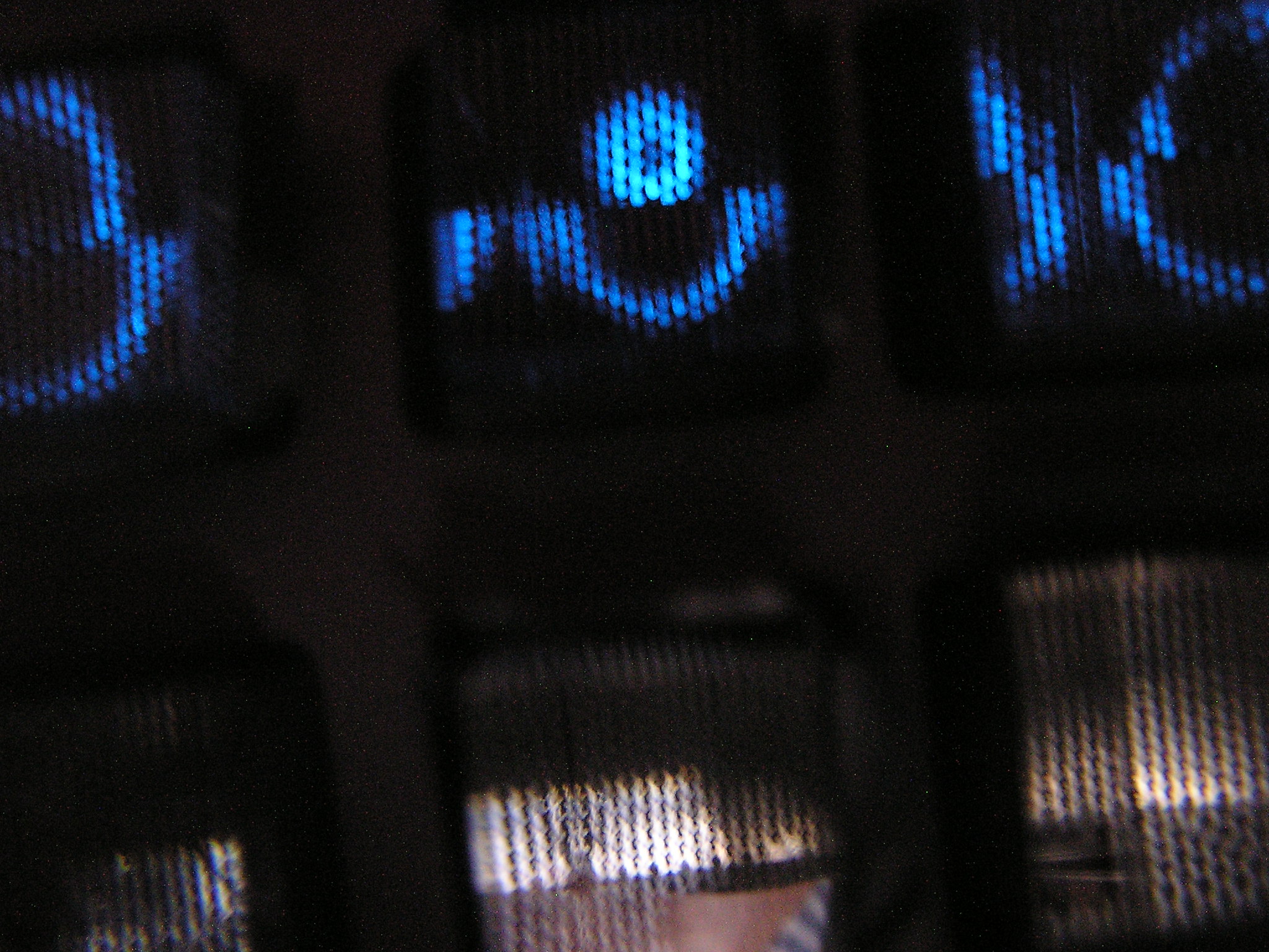
- View of LED light far side, flashing column Media:LED_light1.JPG
- View of LED light far side, adjacent to flashing column Media:LED_light2.JPG
- View of LED light far side, flashing column Media:LED_light3.JPG
- Jig to place LED string for gluing side view Media:LED_glue1.JPG
- Jig to place LED string for gluing side view perspective Media:LED_glue2.JPG
- Jig to place LED string for gluing / remaining glue after gluing and removal Media:LED_glue3.JPG
- LEDs located on the front face of third row from bottom (T3) to simulate illumination from the light guide input Media:PF1010003.JPG