Difference between revisions of "RF Calibration"
From GlueXWiki
(→Fine Time Offsets) |
(→Fine Time Offsets) |
||
| Line 184: | Line 184: | ||
* To determine the final time offsets (and their uncertainties), re-run the <span style="color:#0000FF">RF_online</span> plugin (after checking in the coarse time offsets) on a small sample of data (e.g. 10000 events), and then run the <span style="color:#0000FF">RFMacro_FineTimeOffsets.C</span> macro on the resulting ROOT file: | * To determine the final time offsets (and their uncertainties), re-run the <span style="color:#0000FF">RF_online</span> plugin (after checking in the coarse time offsets) on a small sample of data (e.g. 10000 events), and then run the <span style="color:#0000FF">RFMacro_FineTimeOffsets.C</span> macro on the resulting ROOT file: | ||
| − | ** Below, <span style="color:red"><b>"<run_number>"</b></span> is any run number in the run range in which you are trying to set the constants. | + | ** Below, <span style="color:red"><b>"<run_number>"</b></span> is any run number in the run range in which you are trying to set the constants. The run number is needed to make sure that the new offset values are combined with the appropriate, old offset constants to create new offset values. |
root -l hd_root.root | root -l hd_root.root | ||
Revision as of 18:19, 29 September 2015
Contents
Overview
- The RF signal from the accelerator comes in at a frequency of 499 MHz, regardless of the beam bunch frequency (typically 249.5 MHz). It is multiplexed and read out in 6 different locations; in one channel of each of the following crates:
- F1TDCs: TAGH, FDC, PSC
- CAEN TDCs: TOF
- FADC250s: TAGH, ST
- Since the RF signal is the highest-resolution time measurement for the event (particularly in the TOF CAEN TDC), it is used as a baseline to help line up the timing offsets of the different detector systems.
- Also, during analysis, detected tracks will "vote" on the beam bunch that caused the event, and then it's time can be used as an event start time for computing particle-ID confidence levels.
- Because the RF signal is periodic it is effectively self-analyzing: it can be compared against itself to study our understanding of the timing. It also serves as a good test of whether the TDC → time conversion is working properly.
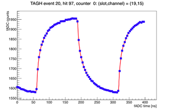
- However, the FADC250 algorithms were not designed to extract the pulse times from signals with a waveform of the RF distribution (degraded square-wave, see plot), so these signals are ignored.
Notes / References
- For questions regarding these procedures, please contact Paul Mattione.
- Link to the RF_online plugin and scripts, which contains all of the code needed for these calibrations: Link
- The ROOT macros for studying the data are located in the calib_scripts subfolder in this plugin directory.
- The logbook entry detailing which channels the RF signals are hooked up to: Link
- A follow up note on their locations (and a correction): Link
- A wiki page detailing which ROCs are which can be found at: Link
RF Calibration Constants
- The following calibration constants are in the CCDB for the RF signal:
| CCDB Table Name/Path | Description |
|---|---|
| PHOTON_BEAM/RF/rf_period | The period of time between beam bunches arriving from the accelerator. |
| PHOTON_BEAM/RF/time_offset | The time difference between the other RF signals and the TOF RF signal. |
| PHOTON_BEAM/RF/time_offset_var | The variance of time_offset. |
| PHOTON_BEAM/RF/time_resolution_sq | The square of the resolution of the measurement of the RF signal. |
- Except for rf_period, each entry is a table with 4 columns (TOF, TAGH, PSC, FDC) and 1 row (the values for that constant).
- Since the TOF RF signal has the best resolution, its time_offset and time_offset_var constants should be 0.
Validating TI-Time Uniformity
- As detailed in GlueX Doc 2686, a copy of the global system clock time is present on each ROC (on the Trigger Interface (TI) board). To check whether they are all consistent with each other, run the RF_online plugin on a small sample of data (e.g. 10000 events), and then run the RFMacro_ROCTITimes.C macro on the resulting ROOT file:
root -l hd_root.root
.L $HALLD_HOME/src/plugins/monitoring/RF_online/calib_scripts/RFMacro_ROCTITimes.C
main();
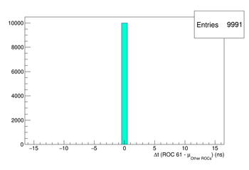
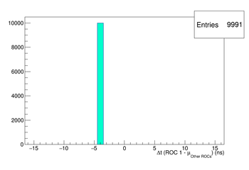
- It will print to screen any ROCs whose system clock is out of time with the average system clock times from the other ROCs. It will also draw the corresponding histograms. ROC 1 (the trigger supervisor crate) is known to be out of time with the others, and is currently being looked into by the Triggering expert.
- If any of the other ROCs are out of time with the others, notify the Triggering expert.
- Example plots:
TDC → Time Conversion
- The details of how to convert the F1TDC and CAEN TDC signals to times are in GlueX Doc 2686. These algorithms are implemented by the DTTabUtilities class (in sim-recon/src/libraries/TTAB).
- F1TDCs: The F1TDC times are converted using the ROC TI time as the reference time. The DF1TDCConfig class contains the necessary constants for performing the conversion. If this class is not present in the data stream, the constants in the CCDB are used (Link). Also, the DF1TDCConfig information in the data stream was incorrect for runs <= 2965, so the CCDB constants are used for these runs as well. Otherwise, the CCDB constants should no longer be used.
- CAEN TDCs: The TDC → time conversion constant for the CAEN TDCs was derived by Ben Raydo and is documented in this email. It is 23.4375 +/- 0.0012 ps. This uncertainty is small enough that a channel-by-channel pulser measurement of the TDC → time conversion constant is unnecessary.
- As mentioned in the GlueX timing document (GlueX Doc 2686), the 6-fold-ambiguity CCDB constant (/TOF/tdc_shift) has been fixed. It is fixed to a constant value of 1, and should not need to be changed.
- This can be checked by running the TOF_TDC_shift plugin on EVIO data.
- As mentioned in the GlueX timing document (GlueX Doc 2686), the 6-fold-ambiguity CCDB constant (/TOF/tdc_shift) has been fixed. It is fixed to a constant value of 1, and should not need to be changed.
Validation
- Since they are periodic, the RF time signals are excellent for checking whether the TDC signals are being properly converted to time. To check this, run the RF_online plugin on a small sample of data (e.g. 10000 events), and then run the RFMacro_TDCConversion.C macro on the resulting ROOT file:
root -l hd_root.root
.L $HALLD_HOME/src/plugins/monitoring/RF_online/calib_scripts/RFMacro_TDCConversion.C
main();
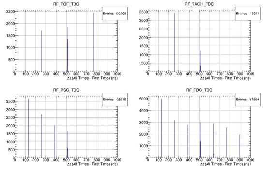
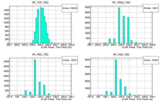
- This macro will draw histograms for each detector system of the time difference between the first RF signal in an event and the times of the subsequent RF signals. Zoom in on these histograms and confirm that the secondary peaks are occurring at the correct times.
- The TOF & TAGH RF signals read out 1/128 times, so the first delta-t peak should be at 128*1000/499 = 256.513 ns.
- The PSC & FDC RF signals read out 1/64 times, so the first delta-t peak should be at 64*1000/499 = 128.257 ns.
- If the RF signals don't arrive at their expected times, notify the online and/or electronics experts.
- Example plots:
RF Time Calibration
RF Signal Period
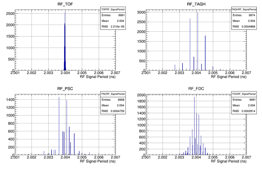
- Because the RF signal is being recorded several times in each channel for each event, the frequency of the RF signal can be determined by comparing these times to each other. It should be about 499 MHz.
- Note that this is not the same as the beam bunch frequency, which is typically 249.5 MHz.
- Remember, as discussed in the section on TDC → Time Conversion, that the signals are read out at a reduced rate.
- To confirm that the RF signal is arriving approximately every 2.004 ns (499 MHz), run the RF_online plugin on a small sample of data (e.g. 10000 events), and then run the RFMacro_SignalPeriod.C macro on the resulting ROOT file:
root -l hd_root.root
.L $HALLD_HOME/src/plugins/monitoring/RF_online/calib_scripts/RFMacro_SignalPeriod.C
main();
- This should produce histograms similar to the following, showing the 2.004 ns signal period:
- If the signal period is not 2.004 ns, notify the electronics expert.
Beam Bunch Period
- At the beginning of each run period, the beam bunch period needs to be determined. It will typically be 4.008 ns (249.5 MHz), but can sometimes be other values (e.g. 2.004 ns (499 MHz) during Fall 2014 data).
- Remember, the period of the beam bunches is not necessarily the same as the period of the RF signal.
- To determine the beam period, run the RF_online plugin on a small sample of data (e.g. 10000 events), and then run the RFMacro_BeamBunchPeriod.C macro on the resulting ROOT file:
root -l hd_root.root
.L $HALLD_HOME/src/plugins/monitoring/RF_online/calib_scripts/RFMacro_BeamBunchPeriod.C
main();
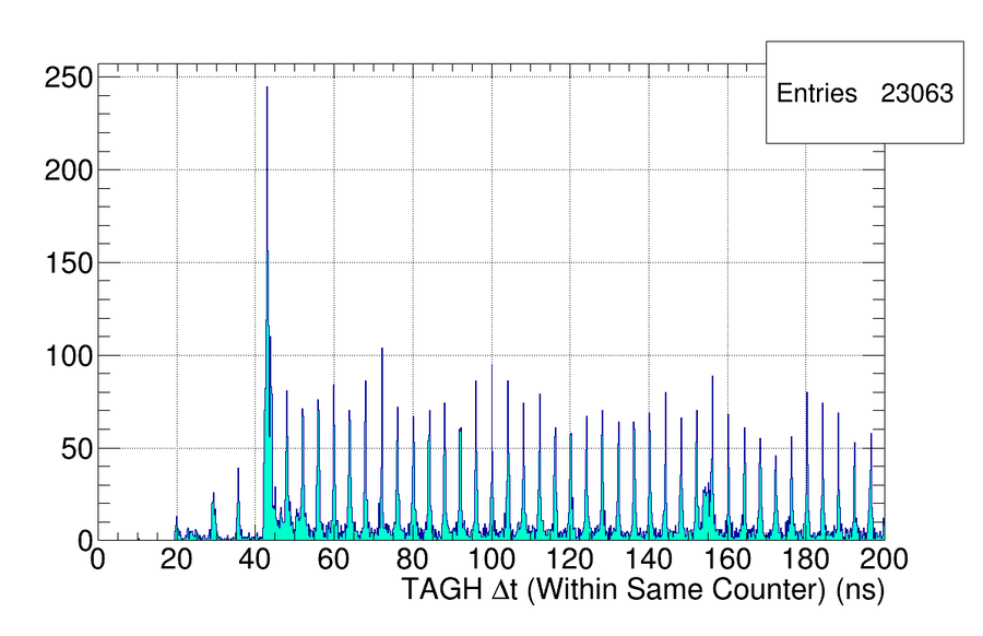
- This will produce a histogram showing the time difference between different tagger hits in the same counter within the same event. It should look similar to the following, where the time difference between the peaks indicates the period of the beam bunches (here 4.008 ns):
- The resolution of the tagger times is not good enough to determine the actual frequency from this histogram. Instead, compare the difference between the peaks to the expected value of the beam period (here, 249.5 MHz = 4.008 ns).
- If the beam bunch period has changed, create a new, single-line text file (e.g. beam_period.txt) containing one number, the value of the new beam bunch period:
4.008016032
- Then check the new constant into the CCDB with the following (using the appropriate run numbers for run_min & run_max):
ccdb add PHOTON_BEAM/RF/rf_period -r <run_min>-<run_max> beam_period.txt #"Beam bunch period"
RF Time Resolution
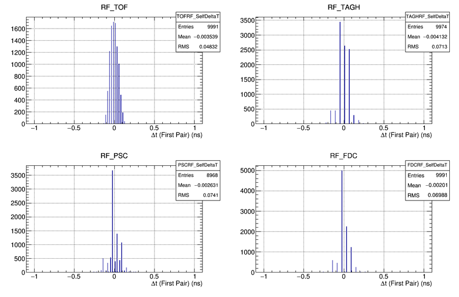
- To study the resolution of the RF time signal, the RF signal can be compared to itself, since the frequency of the signal is known. The difference between the first two RF signals in a given event can be shifted by a multiple of 2.004 ns such that the difference lines up near zero. Doing this for many events gives the resolution of the RF signal measurement.
- This resolution is dominated by the resolution of the readout electronics modules (F1TDCs, CAEN TDCs).
- To do this, run the RF_online plugin on a small sample of data (e.g. 10000 events), and then run the RFMacro_SelfResolution.C macro on the resulting ROOT file:
root -l hd_root.root
.L $HALLD_HOME/src/plugins/monitoring/RF_online/calib_scripts/RFMacro_SelfResolution.C
main();
- It should produce plots similar to the following:
- If these distributions are malformed, then it is likely that the TDC -> time conversion is incorrect. Revisit that step.
- It will also print the time-resolution-squared for each system to screen and to a text file. Check the constants into the database with the following (using the appropriate run numbers for run_min & run_max):
ccdb add PHOTON_BEAM/RF/time_resolution_sq -r <run_min>-<run_max> rf_time_resolution_sq.txt #"time resolution squared"
Coarse Time Offsets
- The timing offsets between the different RF signals can be quite large (on the order of several micro-seconds). Thus the timing offset calibration is separated into two steps: A course alignment and a fine alignment.
- Since the RF signal period is 2.004 ns, you would think that you should just be able to propagate the times to each other (shift by N * 2.004 ns) and take the difference. However, this procedure is sensitive to small inaccuracies in the RF signal period since the times can be offset by several micro-seconds. It's better to do a coarse offset first, and use this method for a fine alignment in the next step.
- To determine the coarse time offsets, run the RF_online plugin on a small sample of data (e.g. 10000 events), and then run the RFMacro_CoarseTimeOffsets.C macro on the resulting ROOT file:
- Below, "<run_number>" is any run number in the run range in which you are trying to set the constants.
root -l hd_root.root
.L $HALLD_HOME/src/plugins/monitoring/RF_online/calib_scripts/RFMacro_CoarseTimeOffsets.C
main(<run_number>);
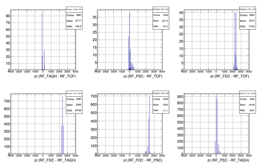
- This should produce histograms similar to the following:
- It will also print the coarse time offsets for each system to screen. These offsets are automatically combined with the current time offsets in the CCDB to produce new time offsets. These values are printed to screen, as well as to a text file. Check these constants into the database with the following (using the appropriate run numbers for run_min & run_max):
- NOTE: When getting the "current" CCDB constants (to update their values), the script uses the "dump" command which dumps the "latest data." If earlier constants are desired for some reason, you must modify the script manually.
ccdb add PHOTON_BEAM/RF/time_offset -r <run_min>-<run_max> rf_coarse_time_offsets.txt #"coarse time offsets"
Fine Time Offsets
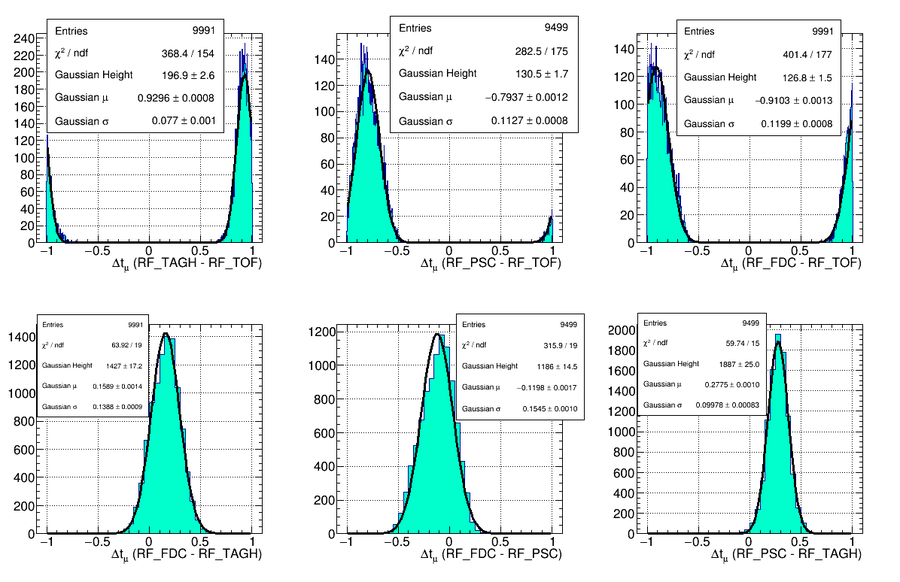
- After performing the coarse time offsets and checking in the constants, fine-grained time offsets can be found by propagating the times from each system to each other by shifting by a multiple of 2.004 ns. This should produce a Gaussian time-difference distribution between +/- 1.002 ns that can be fit to produce the final time-offsets.
- To determine the final time offsets (and their uncertainties), re-run the RF_online plugin (after checking in the coarse time offsets) on a small sample of data (e.g. 10000 events), and then run the RFMacro_FineTimeOffsets.C macro on the resulting ROOT file:
- Below, "<run_number>" is any run number in the run range in which you are trying to set the constants. The run number is needed to make sure that the new offset values are combined with the appropriate, old offset constants to create new offset values.
root -l hd_root.root
.L $HALLD_HOME/src/plugins/monitoring/RF_online/calib_scripts/RFMacro_FineTimeOffsets.C
main(<run_number>);
- This should produce histograms similar to the following, which can be fit to a special function: a sum of two Gaussians with identical heights and widths, and means that are separated by exactly 1000/499 ns:
- The means of this fit are the fine timing offsets, and the mean fit uncertainties are the uncertainties on the offsets. The fit means are automatically combined with the coarse time offsets in the CCDB to produce the final time offsets. These values are printed to screen, as well as to text files. Check these constants into the database with the following (using the appropriate run numbers for run_min & run_max):
- NOTE: When getting the "current" CCDB constants (to update their values), the script uses the "dump" command which dumps the "latest data." If earlier constants are desired for some reason, you must modify the script manually.
ccdb add PHOTON_BEAM/RF/time_offset -r <run_min>-<run_max> rf_fine_time_offsets.txt #"fine time offsets"
ccdb add PHOTON_BEAM/RF/time_offset_var -r <run_min>-<run_max> rf_time_offset_vars.txt #"time offset variances"
Intra-system Jitter
- As seen in the Fine Time Offsets section, the resolution of the time-difference histograms is much larger than you would naively expect from the time resolutions of the individual channels determined in the RF Time Resolution section. This increased uncertainty due to the jitter between the systems means that when reporting the RF time for the event, only a single source should be used.
- Since the TOF RF signal has higher resolution than the other systems, it is used when reporting the RF time during reconstruction (the DRFTime object). If for some reason no signal is present for this channel, the data from the other systems are used, in order of increasing time resolution.
- When reporting an official value for the DRFTime, the average of the RF times from the best system is used. Of course it is not a straight average, but rather, the later times are propagated back to the first time (via multiples of 2.004 ns), and then averaged. This gives a better resolution than just using the first recorded time.
- Log Entry 3342826 has a naive interpretation of the measured widths.
Check Alignment to Tagger Hodoscope
- After the timing offsets for the tagger hodoscope have been determined (by the HLDetectorTiming plugin), the matching between the RF times and the tagger hodoscope can be confirmed by running the RF_online plugin on a small sample of data (e.g. 10000 events), and then run the RFMacro_TaggerComparison.C macro on the resulting ROOT file:
root -l hd_root.root
.L $HALLD_HOME/src/plugins/monitoring/RF_online/calib_scripts/RFMacro_TaggerComparison.C
main();
- This will produce a histogram for each RF source showing the time difference between them and the tagger. If these are not lined up with zero, re-run the HLDetectorTiming plugin to line up the tagger with the RF.
MO Phase Drift
- A note detailing the phase drift of the master oscillator that supplies the RF signal can be found in Log Entry 3340814.
- At the moment the phase drift is small and introduces a negligible uncertainty in the RF time offsets as a function of time. However, it should be monitored to see whether it gets worse and needs to be corrected for. These EPICs variables should be written to the data stream.
