Difference between revisions of "University of Connecticut Active Collimator Station Tutorial"
(→Configuration of the Station) |
|||
| Line 5: | Line 5: | ||
Figures 1 and 2 serve to show the user how the active collimator station is connected to the actcol-station PC. I have labeled various components in Figure 1; their descriptions are below. Figure 2 shows the user how to connect everything to the PC. | Figures 1 and 2 serve to show the user how the active collimator station is connected to the actcol-station PC. I have labeled various components in Figure 1; their descriptions are below. Figure 2 shows the user how to connect everything to the PC. | ||
| − | '''1:''' The signals from the tungsten plates within the active collimator are picked up and transmitted to the amplifiers via an SMA to BNC cable | + | '''1 and 2:''' The signals from the tungsten plates within the active collimator are picked up and transmitted to the amplifiers via an SMA to BNC cable. |
| − | + | ||
| − | + | ||
'''3:''' On the "downstream" end of the amplifiers, there is a BNC to BNC cable that transmits the amplified signals to the "BNC box"(5). There is also a DB9 to Ethernet adapter; an Ethernet cable supplies power and sets the gain. | '''3:''' On the "downstream" end of the amplifiers, there is a BNC to BNC cable that transmits the amplified signals to the "BNC box"(5). There is also a DB9 to Ethernet adapter; an Ethernet cable supplies power and sets the gain. | ||
Revision as of 02:56, 14 January 2014
On January 7th, 2014, the active collimator station (computer name actcol-station) was positioned in room F117 of the CEBAF building at Jefferson Lab. This wiki page serves to teach how the station operates.
Configuration of the Station
Figures 1 and 2 serve to show the user how the active collimator station is connected to the actcol-station PC. I have labeled various components in Figure 1; their descriptions are below. Figure 2 shows the user how to connect everything to the PC.
1 and 2: The signals from the tungsten plates within the active collimator are picked up and transmitted to the amplifiers via an SMA to BNC cable.
3: On the "downstream" end of the amplifiers, there is a BNC to BNC cable that transmits the amplified signals to the "BNC box"(5). There is also a DB9 to Ethernet adapter; an Ethernet cable supplies power and sets the gain.
4: A power splitter. From right to left: power source from power supply, four power sources for the amplifiers, signal from terminal board (6).
5: A BNC to BNC cable connects each amplifier to this "BNC box." The BNC box is then connected to the terminal board (6) and PC via a ribbon cable.
6: The terminal board. See Figure 2 for a better view.
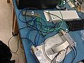
Figure 1
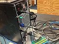
Figure 2


Feel free to contact me at john DOT bartolotta AT uconn DOT edu with any questions.