Basic formalism for X-ray monochromator resolution
The X-ray beam from a synchroton light source like CHESS originates in a small spot of rms typical dimensions of 1.5 mm. The divergence of the beam is of order m/E which is 100 μr for CHESS running at 5.5 GeV. The energy spectrum depends on the beam line.
C1 is a bend-magnet end station, so the spectrum is smooth from a few keV up to a broad maximum around 10 keV, above which it gradually drops off. There is very little intensity left above 50 keV. The spectrum at the left was generated using an online SR spectrum generator on the Lawrence Berkeley web site.
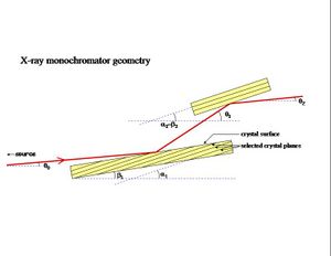
The C1 diffraction end-station is located a distance 25 m from the synchrotron source. At this distance, the vertical divergence of this beam is sufficient to make a beam spot of rms size 3 mm (vertical). The horizontal (bend-plane) divergence angle is defined by slits, so it can be made as large as desired. To increase the vertical size of the beam for these measurements, an asymmetric silicon crystal was used. A asymmetric crystal has a planar surface that is cut at an oblique angle to a set of crystal planes so that the incidence and reflection angles are different with respect to the crystal surface.
Because the reflection takes place within a few microns of the crystal surface, this has the effect of spreading out the beam in the dimension that lies within the scattering plane. The relevant angles are labeled in the figure. The factor by which the beam is expanded is called the asymmetry factor b, defined as

|
(1) |
At the same time as it broadens the beam, the kinematics of diffraction from the asymmetric crystal also decreases the angular divergence of the beam. The combined effect of these two things is to make the source appear to be a factor b further away than it actually is. Of course, this effect is only seen in the dispersion (vertical) direction; the horizontal source size and divergence are not affected. All of this can be expressed by the expression
|
|
(2) |
where the angles are labeled in Fig. 1 above, q is the crystal momentum of the reflection planes, and k is the X-ray energy. Note that (θ-β) and (θ1-β) are the conventional incidence and reflection Bragg angles. In the symmetric crystal case, α=β and the usual condition for equality of incidence and reflection angles holds. Eq. 2 has a solution even when q is far from 2k sin(θ-β), so the diffraction condition must be imposed by the scattering condition
|
|
(3) |
where δq is defined in terms of the rocking curve width δθ as
|
|
(4) |
and θB is the Bragg angle for the selected monochromator reflection. The parameter δq is more convenient for defining the monochromator resolution because it is very nearly constant for a given set of crystal planes, unlike δθ which varies with θB.


