ANSYS simulations
Summary of field simulations for the 30D72 magnet from BNL
The BNL 30D72 magnet has been modeled in Ideas based on the original drawings of the iron cores. The model was imported into ANSYS as a step fiel and used as the basis of a magnetostatic simulation. The side view o the right only shows the left half of the magnet. In the simulation a symmetry plane is inserted in the z=0 plane and only half the magent is calculated. A rectangular box is added to the model which will later represent an air volume. This aids in later meshing the model.


Detailed drawings of the coils were not available so approximatate values needed to be determined from the known specifications of the magnet. The specification states that the magnet will have a maximum field of 2T at an operating current of 2500 A. The number of turns was adjusted to match this. It was assumed that the magnet is made from 1006 steel.

For 2T each 106 turns per coil was required. The assembly drawings indicate that there are 4 layers of conductor per magnet half. For each magnet half there are 2 separate coil packages each with 2 layers of conductors. 106 turns corresponds to about 26 turns per layer. There is no size copper which matches well to the outside dimensions and 26 conductors per layer. 3/4" conductor would correspond to 16 conductors per layer. Clearly more details of the coil are needed. For now it should be assumed the actual current could be 60% higher then what is input to the simulation.
The model was then changed to reflect the suggestion that the top and bottom of the vacuum chamber which is to be inserted in the magnet gap be used to reduce the total gap to 30mm. Iron plates were added to the top and bottom poles such that the gap was reduced to 30mm. A 45 degree chamfer was placed all around the new plates. As the gap is now only 30mm the air gap was removed.

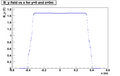
The field was simulated and the current adjusted to give the 1.68T central field requested in the proposal. The field along the inner and outer edge of the pole tip is about 2T which corresponds to a mu of about 70 for 1006 steel. The maximum field in the model is 2.5T which occures at the corners of the chamfer.

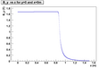
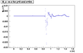
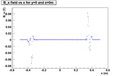
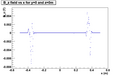
Plots of the magnetic field from the 30D72 magnet after the pole gap is reduced to 30mm
The plots are taken from the ANSYS simulation PS11.dsdp. The field values are read out every 2mm using the postprocessor from CFX.
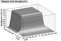
Surface plot
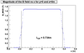
|B| Field vs x
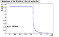
|B| Field vs z
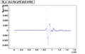
B_x vs z
B_y vs z
B_z vs z
B_x vs x
B_y vs x
B_z vs x


Links up
Return to pair spectrometer page