Difference between revisions of "Beam Test Run Plan"
(→Module Positioning and Rotation) |
(→Primary Goals) |
||
| Line 86: | Line 86: | ||
===Primary Goals=== | ===Primary Goals=== | ||
| − | The primary goal of these measurements is to study the energy and timing response of the BCAL Module near its end and at large angles with respect to the normal. | + | The primary goal of these measurements is to study the energy and timing response of the BCAL Module near its end and at large angles with respect to the normal. (See Module Positioning above for the angular range possible). |
===Secondary Goals=== | ===Secondary Goals=== | ||
Revision as of 11:41, 29 August 2006
Contents
General
Beam Request Document (GlueX-doc-620): Media:Bcal_test.pdf
The task of BCAL is to measure the positions and energies of photons emitted from interactions in the GlueX target from 10-117 degrees with respect to the beam direction. The photon position resolution of BCAL is determined by the time resolution. The timing information from BCAL will also be used to determine the time-of-flight information for charged particles entering BCAL after passing through layers of straw drift tubes (central drift chamber - CDC) surrounding the target.
Scope and Objectives
This is the summary of our test-beam goals for one week of beam time (Sep. 22-30, 2006) delivered to Hall-B during the period in 2006 when the CEBAF accelerator is running at 687 MeV. The electron beam will produce a photon beam using the Hall-B tagger system. Photons of various energies will be used to measure the response of a 4-m-long lead, scintillating fiber (Pb/SciFi) prototype module for the GlueX barrel calorimeter (BCAL). The 687 MeV endpoint energy will provide the minimum photon energies needed for these tests. The module will be mounted on a support system in the Hall-B alcove area. The module will be illuminated at several positions along its length and at several angles, from 0-80 degrees with respect to normal incidence. The data will be anchored to results obtained using cosmic rays and will allow us to measure energy resolution, time resolution and linearity and will also allow a validation of our Monte Carlo simulations.
Goals
- Measure the energy resolution of the center of the module at normal incidence and also determine the linearity over the range of photon energies from 137 to 653 MeV (see Table 1).
- Measure the timing resolution at the center of the module at normal incidence.
- Repeat the above energy and timing resolution measurements at the center of the module for four angles of incidence at and between 45-80 degrees.
- Repeat the above energy and timing resolution measurements at normal incidence and at four angles of incidence at and between 45-80 degrees for four positions from the center to the end of the module.
Prototype Module
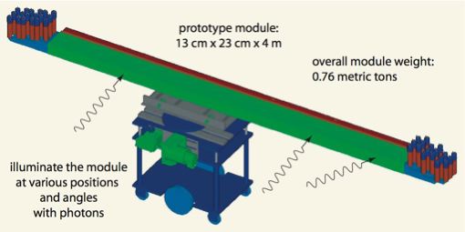
A 4~m-long prototype module, termed Module 1 was constructed in 2004 and this will be tested in the 2006 Test Beam at Hall-B. The module, shown schematically in the figure below, has a rectangular cross section of 13 x 23.0 cm^2 active area of Pb/SciFi. Over 70 km of double-clad fiber and 12 kg of epoxy were used in its construction. The scintillating fibers were made by PolHiTech and are blue-emitting with a peak emission wavelength of 420 nm and an attenuation length of ~350 cm. The fibers have a diameter of 1 mm (with 3% and 1% being the thickness of the first/inner and second/outer cladding layers) and the thickness of the lead sheets is 0.5 mm. The module has 186 planes of Pb/SciFi. The composite has a Pb:SciFi:Epoxy ratio of 37:49:14 and an overall density of ~ 5 gm/cm^3 and a radiation length (X_0) of 1.5 cm. Each layer of the module to be tested has 96 SciFi's spaced 1.38 mm apart (center-to-center) and the layers are such that they do not present any gaps in SciFi coverage thus presenting a uniform SciFi density across the shower path. The total weight of the module is 760 kg (including associated aluminum and steel plates) and the support carriage weighs an additional 550 kg. The former rests on top of the latter and both are supported by a cart that has a motorized, computer-driven, remote-controlled turn table.
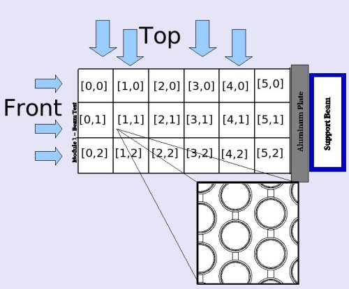
For purposes of the beam tests, the readout will be based on a segmentation scheme of 3 x 6 light guides, each with a cross section of 4 x 4 cm^2, for a total of 36 channels. The channels are grouped in six (0-5) layers (depth, as the beam sees it) and three sectors (0-2) (width). The PMTs are Philips XP2020 (layers 0-2, front nine on each side - 18 in total) and Burle 8575 (layers 3-5, back nine on each side - 18 in total). This segmentation has been studied via Monte Carlo simulations of the detector and is shown schematically below. The choice of phototube is based on providing the best timing measurement and this is why the XP2020 are mounted on the front half of the Module, where the energy deposition is greatest. The detailed labelling of the PMTs and cables will be indicated in the GlueX E-Log and will be based on Hall-B orientation into North (right - as the particle travels) and South (left) ends.
Module Positioning and Rotation
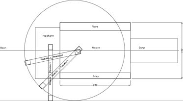
The figure below schematically shows the 4~m-long BCAL module in several positions in the Hall-B alcove needed to achieve the beam test goals. The carriage and cart position the module so that the beam can enter at any point along the face of the module, but allowing a different range of angles at each point along the length, due to space restrictions of the alcove. The platform in front of the alcove has been modified for this setup and a steel plate has been installed as flooring: it stradles the platform and alcove.
The angle of incidence (with respect to normal) can be set to:
- between 10-25o in the alcove near one end of the BCAL
- between 10-45o in the alcove at 35-50cm from the end of the BCAL
- between 70-90o on the platform near the middle of the BCAL.
These numbers will be checked and further refined by Eric, a week before the run. In the interim, the H-B engineers will move a large bundle of cables from the south railing of the platform to a higher point after installing a support cable. This change will allow the BCAL to overhang the south railing at angles near the normal.
Calibrations/Checks with Cosmics
The initial calibration of the BCAL prototype module (Module 1) will be accomplished using cosmics...
Trigger/DAQ Tests
PMT Checks
PMT Gain Matching
Cosmics Runs
Pedestals and timing offsets can be determined using cosmics...
Calibrations/Checks with Beam
Trigger and Commissioning
PMT Checks
PMT Gain Matching
===DAQ Monitoring Histograms
Test Beam
Hall-B and Tagger
| Photon Energy (MeV) | Fraction of electrons through magnet | Fraction of photons through collimator |
| 653 | 0.872 | 0.067 |
| 618 | 0.934 | 0.066 |
| 550 | 0.961 | 0.066 |
| 344 | 0.977 | 0.070 |
| 137 | 0.983 | 0.072 |
| Table 1: Hall-B Tagger characteristics at an endpoint energy of 687 MeV | ||
During the initial stages of beam in Hall-B, the BCAL will be positioned so that the beam impacts at its center, and at a 90 degree angle...
Primary Goals
The primary goal of these measurements is to study the energy and timing response of the BCAL Module near its end and at large angles with respect to the normal. (See Module Positioning above for the angular range possible).
Secondary Goals
The secondary goal is to extract the effective speed of light in the fibers and the attenuation length, from measurements along its length. The latter would be a first-time extraction using photons and will be compared with past cosmics and charged-particle measurements at TRIUMF.
Sample Histograms
Sample histograms of the measured and simulated energy deposition and timing information in the readout cells of the BCAL Module will be continuously updated on the Wiki. Have a look of the first simulated histograms.
How-to Instructions
How do I change the high voltage on the PMTs? How do I make a log book entry? What do I need to know for the rotation or translation of the BCAL Module? Have a look at our extensive list of HOWTOs.
Safety
Procedures
Documents
Elton, Elliott please adjust the links to the final TOSP and ESAD documents below, to match your uploaded PDF files (use 'upload file' link from the 'toolbox' menu on the left side of our Wiki pages.
Temporary Operational Safety Procedure (TOSP): Media:TOSP.pdf
Experimental Safety Assessment Document (ESAD): Media:ESAD.pdf


