Difference between revisions of "CDC transfer func attempt"
m (Text replacement - "http://argus.phys.uregina.ca/cgi-bin/private" to "https://halldweb.jlab.org/doc-private") |
|||
| (39 intermediate revisions by one other user not shown) | |||
| Line 1: | Line 1: | ||
{| border="0" cellpadding="2" | {| border="0" cellpadding="2" | ||
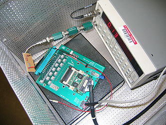
| − | |[[Image: | + | |[[Image:cdctransfnsetup1.jpg|thumb|x250px|Setup ]] |
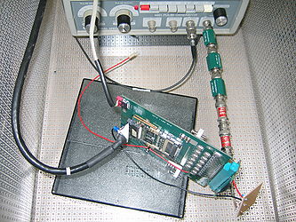
| − | |[[Image: | + | |[[Image:cdctransfnsetup2.jpg|thumb|x250px|Setup (GS 4001)]] |
| − | + | ||
|} | |} | ||
| + | |||
| + | <h4>Circuit</h4> | ||
| + | {| border="0" cellpadding="2" | ||
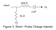
| + | |[[Image:cdc_charge_inj.png|thumb|x100px|Charge injection circuit from Fernando's [https://halldweb.jlab.org/doc-private/DocDB/ShowDocument?docid=1364 GlueX-doc-1364] ]] | ||
| + | |} | ||
| + | |||
| + | Actual component values used were... 51.1 Ohms, 908 Ohms and 2pF. | ||
| + | |||
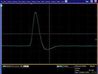
| + | The aim is to inject a charge impulse into the electronics chain and measure its response. | ||
| + | |||
| + | <h4>Early results</h4> | ||
| + | {| border="0" cellpadding="2" | ||
| + | |- Repeated, minus a few attenuators (used attn x5 to go from 0.5V to 0.1V) | ||
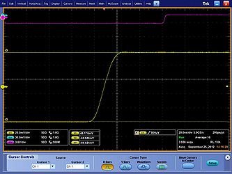
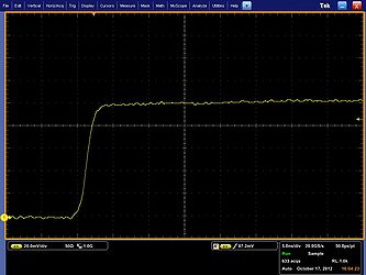
| + | |[[Image:pulser_100mV_input_av.jpg|thumb|x250px|100mV leading edge of sq wave step up (yellow) and trigger from pulser (purple) - average ]] | ||
| + | |} | ||
| + | {| border="0" cellpadding="2" | ||
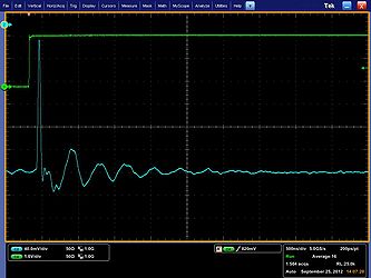
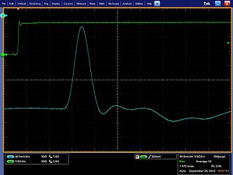
| + | |[[Image:shaper_output.jpg|thumb|x250px|output of shaper - average ]] | ||
| + | |[[Image:shaper_output_z.jpg|thumb|x250px|output of shaper - expanded time scale ]] | ||
| + | |- | ||
| + | |||
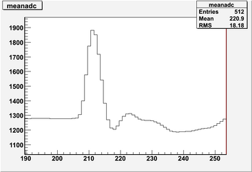
| + | |[[Image:fadc_output_average_new.png|thumb|x250px|output of fadc - average ]] | ||
| + | |[[Image:fadc_output_average_new_z.png|thumb|x250px|output of fadc - expanded time scale ]] | ||
| + | |} | ||
| + | |||
| + | <h4>Final results</h4> | ||
| + | Borrowed Phillips 5771 (no attenuators needed) | ||
| + | {|border="0" cellpadding="2" | ||
| + | |- Input pulse (100mV square wave) | ||
| + | |[[Image:pulse_single.jpg|thumb|x250px|pulser output - single ]] | ||
| + | |} | ||
| + | {|border="0" cellpadding="2" | ||
| + | |- Input pulse (100mV square wave) | ||
| + | |[[Image:pulse_av.jpg|thumb|x250px|pulser output - average ]] | ||
| + | |[[Image:pulse_av2.jpg|thumb|x250px|pulser output - average ]] | ||
| + | |} | ||
| + | |||
| + | |||
| + | {| border="0" cellpadding="2" | ||
| + | |[[Image:pm5771_shaper_single.jpg|thumb|x250px|output of shaper - single ]] | ||
| + | |} | ||
| + | |||
| + | {| border="0" cellpadding="2" | ||
| + | |[[Image:pm5771_shaper_av.jpg|thumb|x250px|output of shaper - average ]] | ||
| + | |[[Image:pm5771_shaper_av2.jpg|thumb|x250px|output of shaper - average]] | ||
| + | |} | ||
| + | |||
| + | {| border="0" cellpadding="2" | ||
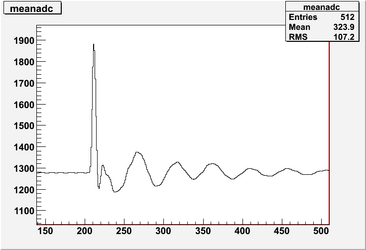
| + | |[[Image:run_31491_adc.png|thumb|x250px|fADC data ]] | ||
| + | |[[Image:run_31491_upsampledadc.png|thumb|x250px|upsampled fADC data]] | ||
| + | |} | ||
| + | |||
| + | <h4>Fitted function</h4> | ||
| + | {| border="0" cellpadding="2" | ||
| + | |[[Image:run_31491_meanupsampledadc.png|thumb|x250px|mean of upsampled fADC data]] | ||
| + | |[[Image:run_31491_fit.png|thumb|x250px|fitted function]] | ||
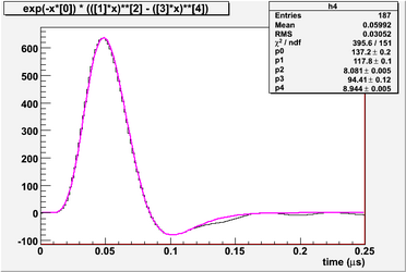
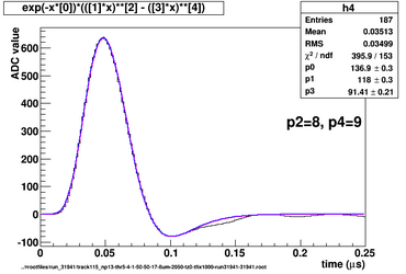
| + | |[[Image:run_31941_fit2.png|thumb|x250px|blue=refit with powers fixed, pink= pars 137, 118, 8, 91.4, 9]] | ||
| + | |} | ||
| + | |||
| + | Beware typos in filenames, this was run #31941! | ||
| + | |||
| + | |||
| + | Input charge: 2 pF x 103 mV = 206 fC | ||
| + | |||
| + | Input current: divide by 12ns peaking time of preamp: 206 fC / 12 ns = 17.2 uA | ||
| + | |||
| + | |||
| + | Peak value of output data is 635 adc_units ~ 635 * 495 mV / 4096 = 76.7 mV | ||
| + | |||
| + | Electronics gain is 76.7 mV / 206 fC = 0.37 mV/fC | ||
| + | |||
| + | (Gain of preamp alone measured earlier (before modifications) by FJB as 0.57 mV/fC) | ||
| + | |||
| + | |||
| + | Convert to current using 50 Ohm resistance: 76.7 mV / 50 Ohm = 1.53 mA | ||
| + | |||
| + | |||
| + | Current gain is 1.53 mA / 17.2 uA = 89.0 | ||
| + | |||
| + | |||
| + | Integrated value of output data is 19.03 adc_units.us ~ 19.03 * 495 mV / 4096 = 2.30 mV.us | ||
| + | |||
| + | Convert to charge using 50 Ohm resistance: 2.3 mV.us / 50 Ohm = 0.046 mA.us = 0.046 nC = 46 pC | ||
| + | |||
| + | |||
| + | Charge gain is 46 pC / 206 fC = 223 | ||
| + | |||
| + | |||
| + | To convert histograms of summed ADC data (with 8ns sample time) to charge, multiply by 8 ns * 46 pC / 19.03 us = 19.3 fC | ||
| + | |||
| + | |||
| + | Garfield uses uA for signals, but I want to see the resulting histograms in adc units, for direct comparison with cosmics data. So... I need to convert my impulse response to input of 1 uA, ie use (1 / 17.2) * fitted function above as the transfer function.?? (Fitted function already includes current gain x 89). | ||
| + | |||
| + | The remaining gain factor needed to match garfield adc data to real life data is the gas gain. | ||
Latest revision as of 16:48, 24 February 2017
Circuit
 Charge injection circuit from Fernando's GlueX-doc-1364 |
Actual component values used were... 51.1 Ohms, 908 Ohms and 2pF.
The aim is to inject a charge impulse into the electronics chain and measure its response.
Early results
Final results
Borrowed Phillips 5771 (no attenuators needed)
Fitted function
Beware typos in filenames, this was run #31941!
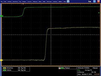
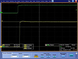
Input charge: 2 pF x 103 mV = 206 fC
Input current: divide by 12ns peaking time of preamp: 206 fC / 12 ns = 17.2 uA
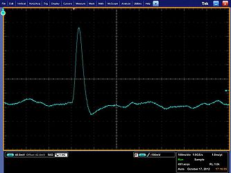
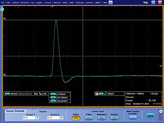
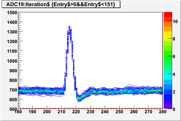
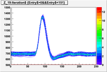
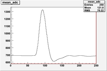
Peak value of output data is 635 adc_units ~ 635 * 495 mV / 4096 = 76.7 mV
Electronics gain is 76.7 mV / 206 fC = 0.37 mV/fC
(Gain of preamp alone measured earlier (before modifications) by FJB as 0.57 mV/fC)
Convert to current using 50 Ohm resistance: 76.7 mV / 50 Ohm = 1.53 mA
Current gain is 1.53 mA / 17.2 uA = 89.0
Integrated value of output data is 19.03 adc_units.us ~ 19.03 * 495 mV / 4096 = 2.30 mV.us
Convert to charge using 50 Ohm resistance: 2.3 mV.us / 50 Ohm = 0.046 mA.us = 0.046 nC = 46 pC
Charge gain is 46 pC / 206 fC = 223
To convert histograms of summed ADC data (with 8ns sample time) to charge, multiply by 8 ns * 46 pC / 19.03 us = 19.3 fC
Garfield uses uA for signals, but I want to see the resulting histograms in adc units, for direct comparison with cosmics data. So... I need to convert my impulse response to input of 1 uA, ie use (1 / 17.2) * fitted function above as the transfer function.?? (Fitted function already includes current gain x 89).
The remaining gain factor needed to match garfield adc data to real life data is the gas gain.
