FCALPhotos
Requirements
The cell wall must hold and shield the 2800 PMTs that are used to read out the lead glass blocks. We expect the a stray field from the GlueX solenoid to be a couple hundred Gauss in the vicinity of the FCAL. To shield from this, the PMTs will need to be recessed about a photocathode diameter ( ~2.5 cm) back into the cell wall tubes. To achieve this while improving light collection efficiency we plan to use aluminized cylindrical light pipes or light guides to connect the PMTs to the lead glass. The light pipes will be glued to the end of the PMT and will be coupled to the lead glass using a Sylgard cookie. The addition of light guides and the need of a serviceable optical joint between the PMT and lead glass are the main technical challenges in the GlueX design that did not exist in the E852 or RadPhi designs.
To accommodate this design the cell wall and base must satisfy a variety of mechanical constraints including:
- provide soft iron enclosure for PMTs
- allow for +- 1/16" variance in length of assembled PMT and base
- permit variance on concentricity of PMT pin pattern and glass envelope
- apply pressure on Sylgard optical joint between light guide and lead glass bar
- minimize production costs by utilizing stock tubing materials (tubing) wherever possible
- allow PMTs and bases to be serviced (replaced)
- PMT FEU-84-3
- 3cm diameter photo cathode
- length about 110mm (without pins)
- case diameter not more than 1.34" (34.04mm)
Design
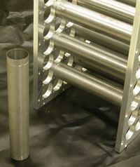
The current GlueX design is based of a design used for both the E852 and RadPhi cell walls. It consists of two thin plates with holes drilled at the PMT locations. The plates are then connected with soft iron sleeves that help magnetically shield the enclosed tubes. The void in between the plates and outside of the tubes is filled with epoxy to make the entire structure mechanically rigid.
Preliminary mechanical drawings for a GlueX cell wall in the style of E852 and RadPhi cell wall were made by Eric Scott and can be found here. The idea is that bases and PMTs (pictured to the right) would fit inside of the tubes and the square metal base would screw into the back plate of the cell wall. This design, however, does not include a mechanism for putting pressure on the light guide optical joint.
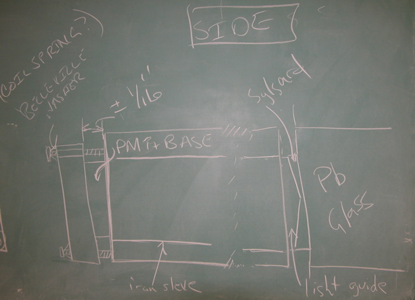
One proposal for extending this design to allow a spring loaded joint is sketched on the blackboard below. The cell wall would be rigidly coupled to the device that holds the lead glass bars. A base/tube/light guide assembly is then slid into the iron sleeve of the cell wall and seated against the block. The screws are inserted through either coil springs or Belleville washers, through the base plate, and into the cell wall. Compression between the screw head and the aluminum plate on the PMT base provides pressure on optical joint. Variation in the distance that the base plate stands off the cell wall accommodates length variation in the base/tube assembly. Applied pressure is determined by tightening the screws and is independent of base/tube length.


