Difference between revisions of "FCAL Magnetic Shield Design"
From GlueXWiki
| Line 2: | Line 2: | ||
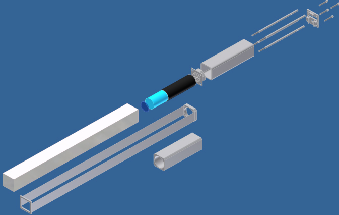
An exploded view of the block, PMT, base assembly: | An exploded view of the block, PMT, base assembly: | ||
| + | |||
[[Image:Fcal_small_shield.jpg]] | [[Image:Fcal_small_shield.jpg]] | ||
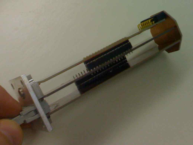
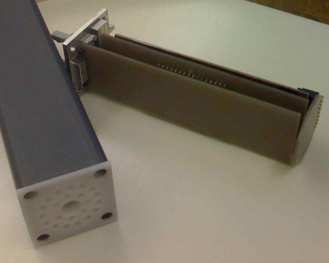
The new shield design leaves the PMT base unshielded. This provides more physical space for the base itself. The base can be made rectangular which allows several independent cards to be connected through headers instead of the flex circuit. This reduces fabrication cost, increases durability, and makes maintenance of the PMT electronics easier. | The new shield design leaves the PMT base unshielded. This provides more physical space for the base itself. The base can be made rectangular which allows several independent cards to be connected through headers instead of the flex circuit. This reduces fabrication cost, increases durability, and makes maintenance of the PMT electronics easier. | ||
| + | |||
[[Image:Cw_base_mech_1.jpg]] | [[Image:Cw_base_mech_1.jpg]] | ||
[[Image:Cw_base_mech_2.jpg]] | [[Image:Cw_base_mech_2.jpg]] | ||
Latest revision as of 16:40, 2 April 2009
Below are some drawings and photographs of both the FCAL magnetic shield and the PMT base.
An exploded view of the block, PMT, base assembly:
The new shield design leaves the PMT base unshielded. This provides more physical space for the base itself. The base can be made rectangular which allows several independent cards to be connected through headers instead of the flex circuit. This reduces fabrication cost, increases durability, and makes maintenance of the PMT electronics easier.


