FDC geometry study
From GlueXWiki
- The baseline geometry (GeomA) is Hall-D Geometry V4 but with CDC GeomC
- Configuration of chambers: U (0 degrees), V (+60 degrees), W (-60 degrees)
- No half-cell offset between neighboring wire planes.
- Alternate geometry GeomB
- Configuration of chambers: UU' (0 degrees), VV'(-60 degrees), WW'(+60 degrees)
- Half-cell offset between primed and unprimed chambers
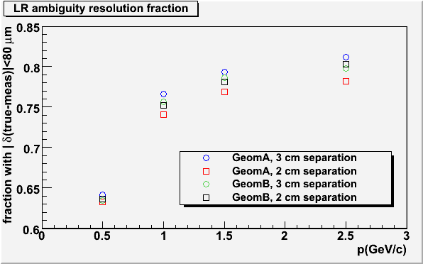
- In both cases I studied 3 cm separation between wire planes (nominal geometry) and 2 cm separation.
- Single pion tracks (p=0.5,1.0,1.5,2.5 GeV/c) generated from the center of the target and analyzed with the standard reconstruction
- The Lorentz effect was turned on, but no other smearing was applied
- The Riemann Fit was used to fit segments and determine the sign for the correction for the Lorentz effect
- Full track reconstruction with standard (ALT1) least squares fitter (time-based, but with uncorrected positions along the wires)
- Check for probability of correct LR assignment in segment fitting: require difference between reconstructed position along wire and true position
to be less than 80 microns. Without the stagger the wider separation between wire planes is favored, but with the stagger the difference between the 2cm and 3cm configurations is small.
- Comparison of transverse momentum resolution for the four geometries.
