Mini BCAL Channel Study
From GlueXWiki
The mini BCAL Module tests
On 3rd March 2023, Chris set up a LED pulsar box to verify the working of the SiPM modules that will be used for the mini BCAL EIC test.
- Module-49 and Module-50 used are spares for the BCAL modules for 2011 that were tested during this study.
- Module-50 was tested however, channels 3 and 4 showed very small amplitudes for both Upstream and downstream, probably indicating that the bias voltage set were not right for them.
The setup
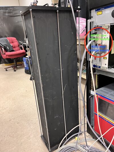
The pulsar box was a dark light-tight box with a blue LED constantly flashing from the bottom. The SiPM modules are mounted on the top, with a casket and a black cloth to seal off any light leaks into the system, Voltage supplies are given by the BCAL distribution boxes as shown in [Slide 12]. The pulsar box is shown on the below.
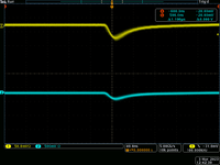
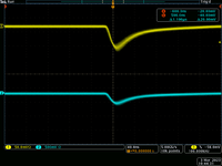
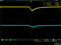
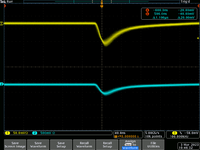
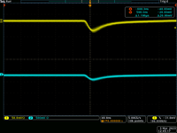
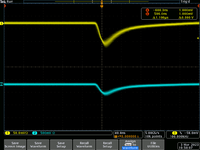
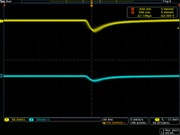
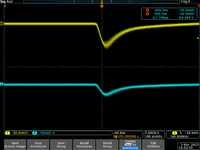
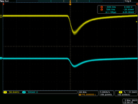
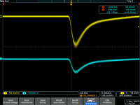
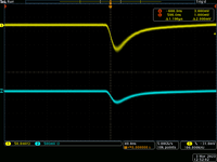
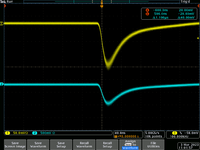
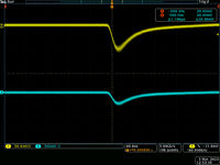
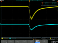
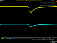
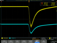
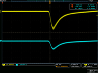
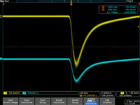
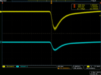
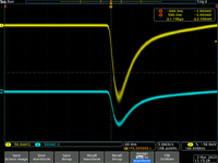
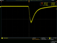
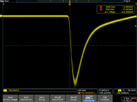
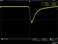
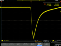
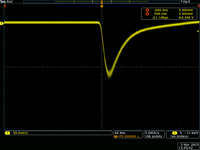
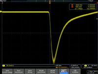
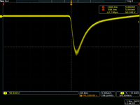
A table summarizing the result of the test is shown below
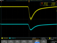
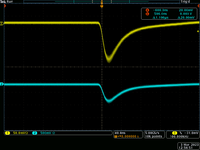
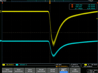
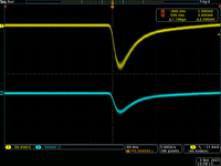
| Upstream Channel | Upstream Signal (Supply 74 V) | Upstream Properties | Downstream Channel | Downstream Signal (Supply 74 V) | Downstream Properties |
|---|---|---|---|---|---|
| AU0 | a | AD0 | a | ||
| AU1 | AD1 | ||||
| AU2 | AD2 | ||||
| AU3 | AD3 | ||||
| AU4 | AD4 | ||||
| AU5 | AD5 | ||||
| AU6 | AD6 | ||||
| AU7 | AD7 | ||||
| AU8 | AD8 | ||||
| AU9 | AD9 | ||||
| AU10 | AD10 | ||||
| AU11 | AD11 | ||||
| AU12 | AD12 | ||||
| AU13 | AD13 | ||||
| AU14 | AD14 | ||||
| AU15 | AD15 |
