Difference between revisions of "Minutes-11-4-2010"
(→Engineering) |
|||
| (11 intermediate revisions by the same user not shown) | |||
| Line 7: | Line 7: | ||
#* Frame lamination | #* Frame lamination | ||
# Electronics (Fernando, Chris, Roger) | # Electronics (Fernando, Chris, Roger) | ||
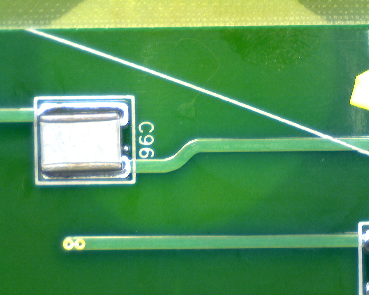
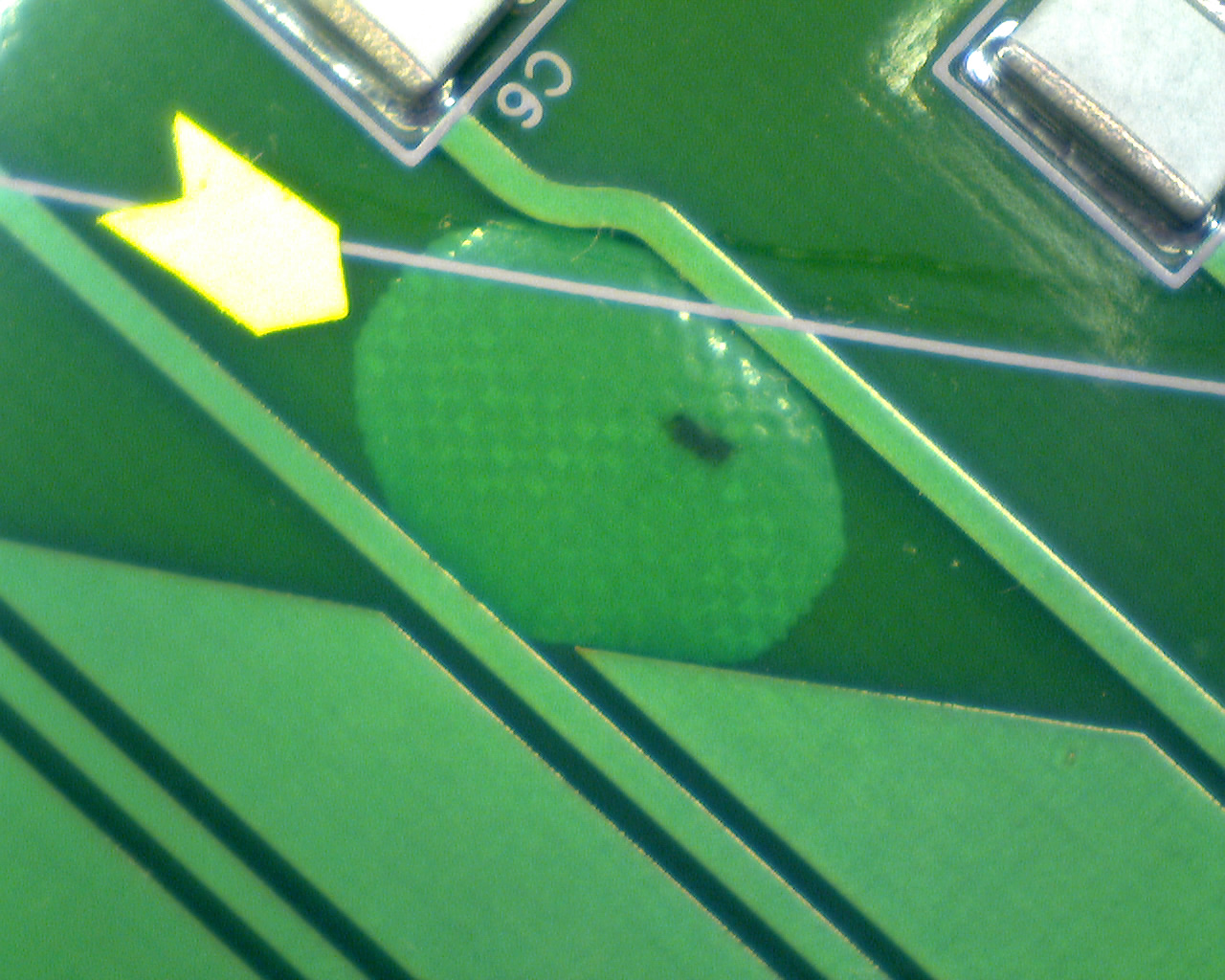
| − | #* Update on PCBs | + | #* Update on PCBs: [http://www.jlab.org/Hall-D/detector/fdc/images/Delamination1.jpg delaminated PCB1] and [http://www.jlab.org/Hall-D/detector/fdc/images/Delamination2.jpg PCB2] |
#* Cathode foil and rigid-flex procurement | #* Cathode foil and rigid-flex procurement | ||
#* Cathode foil inspection plan | #* Cathode foil inspection plan | ||
| Line 14: | Line 14: | ||
#* Other | #* Other | ||
# Full-scale prototype tests | # Full-scale prototype tests | ||
| − | #* status, timing with fADC125 (Beni) | + | #* status, timing with fADC125 (Beni)[http://www.jlab.org/Hall-D/detector/fdclog/ FDC Log Book, page 535] |
| − | #* wire offset studies (Lubomir) | + | #* wire offset studies (Lubomir)[http://www.jlab.org/Hall-D/detector/fdclog/ FDC Log Book, pages 534 and 536] |
# Other | # Other | ||
| − | |||
= Minutes = | = Minutes = | ||
| Line 25: | Line 24: | ||
== Production == | == Production == | ||
| − | - The company will start bringing materials for the clean room on Nov 24. The AC for the whole area will be installed by Dec 7. Before that for the lamination we will use mostly the office (low humidity <40%) and the granite tables outside for vacuum bagging if the humidity is low. That was not the case today. | + | - The company will start bringing materials for the clean room on Nov 24. The AC for the whole area will be installed by Dec 7. Before that for the lamination we will use mostly the office (low humidity <40%), and the granite tables outside for vacuum bagging if the humidity is low. That was not the case today. |
- We got all the wire frames (32) and spacer rings (30). 17 wire frames laminated; 14 are back at Vision machine for fly cut. | - We got all the wire frames (32) and spacer rings (30). 17 wire frames laminated; 14 are back at Vision machine for fly cut. | ||
| Line 31: | Line 30: | ||
== Electronics == | == Electronics == | ||
| − | - Chris: by Wednesday we will have all the PCBs populated. The company sent two pictures (link above) | + | - Chris: by Wednesday we will have all the PCBs populated. The company sent two pictures (link above) showing delaminations on two of the boards. They claim the delamination was there when the boards arrived. But Chris would have seen it!? Roger: the heating cycle they use may cause delamination. Chris will ask |
| + | the company for information about this. | ||
| − | - | + | - Ultrasonic cleaning: according to Chris 6.6gal Vigon costs $285; we need 14gal. Not clear how often we have to change it. |
| − | + | ||
| − | - | + | - Roger: the cathode foil Gerber files will be sent right after the meeting. The extra connectors were included. Will have the first article by Dec 3. |
| − | + | Roger got two quotations and two "no-bids" for the rigid-flex which is good enough for the submission of the PR tomorrow. | |
| + | |||
| + | - We negotiated with Hall B to use a corner in their clean room for cathode foil inspection for two weeks in total. They need a schedule and a list of the people that will work there. Before that we need to decide what kind of tests we want to do. Beni: measuring connectivity of all the strips is needed for the first article. Eugene: resistivity measurements (2 Ohms per strip) and we may look for variations of the Cu thickness. Glenn: difficult for low resistivity. Roger: we may use camera for inspection. Lubomir will consult also Fernando and other people that have done this before, and will make a plan and list of the people. | ||
| − | + | == Engineering == | |
| − | + | ||
| − | - | + | - Movement system. David: The USB-ISA connection is not trivial and requires significant efforts. Two people from "Cross-Automation" came today to 126 to discuss the interface to the stepper motor. They could provide a controller system for $3-5K that will work for us. Also, they could provide or assist in developing the software but we are not ready with the requirements. Some free software interface exists and Lubomir will look to estimate how easy will be for us to develop the software. |
| − | + | - Bill send the strongback back to the machine shop for some modifications. Working on the spool holder and the weights (out of steel). Bill explained how the | |
| + | movement system will be attached to the granite table. This may require drilling additional holes in the granite, but this time horizontally. | ||
| − | - Wire | + | - Wire tensions: Lubomir investigated to effect of the wire offsets on the gain and on the strip signals. As long as the tension is above 15g on the sense wires and above 60g on the field wires, the effects on the chamber operation are small. We can use as nominal tensions: 20g and 132g based on Dan's estimates and Bill's correction of the field wire linear density. However, too high tension on the field wire is not needed (since we can tolerate some difference in the gravitational sag) and may cause frame deformation. Bill will estimate the deformation effects and after that we can decide about the tension values. |
| − | + | ||
| − | + | ||
== Full-scale prototype tests == | == Full-scale prototype tests == | ||
| − | - | + | - Beni connected the trigger logical signal into the fADC to measure the trigger time w.r.t. fADC clock. Most of the time, there's only one sample in between the min and max value of the rising edge. This was not expected, since the shaping time must be ~35ns!? Beni used the events with two samples to estimate the slope which was used for the events with one sample to estimate the trigger time. Using such procedure, the distribution of the trigger time between the samples is very flat and the peaks in the drift time distribution disappear (page 535). |
| − | + | ||
| − | + | ||
| − | + | ||
| − | + | ||
| − | - | + | - Measurements with the bottom chamber showed the vertical positions of the wires look much better than for the top chamber (page 536). No explanation yet. There's ~0.2mm offset for the bottom, compared to ~1mm for the top chamber. Lubomir did also Garfield simulations (page 534) of the strip signals as a function of the avalanche azimuthal angle around the wire and also for different wire offsets. The angle variations are of the order of few %. 1mm offset of the wire up would give a top/bottom strip ratio of ~1.5 what we actually measure for the top chamber. |
Latest revision as of 18:39, 4 November 2010
November 4, 2010 FDC meeting
Contents
Tentative Agenda
- Production (David)
- Blue Crab status
- Frame lamination
- Electronics (Fernando, Chris, Roger)
- Update on PCBs: delaminated PCB1 and PCB2
- Cathode foil and rigid-flex procurement
- Cathode foil inspection plan
- Engineering (Bill, David)
- Wire stringing status; position measurement system.
- Other
- Full-scale prototype tests
- status, timing with fADC125 (Beni)FDC Log Book, page 535
- wire offset studies (Lubomir)FDC Log Book, pages 534 and 536
- Other
Minutes
Participants: Eugene, Bill, Glenn, Simon, Chris, Roger, David, Beni, and Lubomir.
Production
- The company will start bringing materials for the clean room on Nov 24. The AC for the whole area will be installed by Dec 7. Before that for the lamination we will use mostly the office (low humidity <40%), and the granite tables outside for vacuum bagging if the humidity is low. That was not the case today.
- We got all the wire frames (32) and spacer rings (30). 17 wire frames laminated; 14 are back at Vision machine for fly cut.
Electronics
- Chris: by Wednesday we will have all the PCBs populated. The company sent two pictures (link above) showing delaminations on two of the boards. They claim the delamination was there when the boards arrived. But Chris would have seen it!? Roger: the heating cycle they use may cause delamination. Chris will ask the company for information about this.
- Ultrasonic cleaning: according to Chris 6.6gal Vigon costs $285; we need 14gal. Not clear how often we have to change it.
- Roger: the cathode foil Gerber files will be sent right after the meeting. The extra connectors were included. Will have the first article by Dec 3. Roger got two quotations and two "no-bids" for the rigid-flex which is good enough for the submission of the PR tomorrow.
- We negotiated with Hall B to use a corner in their clean room for cathode foil inspection for two weeks in total. They need a schedule and a list of the people that will work there. Before that we need to decide what kind of tests we want to do. Beni: measuring connectivity of all the strips is needed for the first article. Eugene: resistivity measurements (2 Ohms per strip) and we may look for variations of the Cu thickness. Glenn: difficult for low resistivity. Roger: we may use camera for inspection. Lubomir will consult also Fernando and other people that have done this before, and will make a plan and list of the people.
Engineering
- Movement system. David: The USB-ISA connection is not trivial and requires significant efforts. Two people from "Cross-Automation" came today to 126 to discuss the interface to the stepper motor. They could provide a controller system for $3-5K that will work for us. Also, they could provide or assist in developing the software but we are not ready with the requirements. Some free software interface exists and Lubomir will look to estimate how easy will be for us to develop the software.
- Bill send the strongback back to the machine shop for some modifications. Working on the spool holder and the weights (out of steel). Bill explained how the movement system will be attached to the granite table. This may require drilling additional holes in the granite, but this time horizontally.
- Wire tensions: Lubomir investigated to effect of the wire offsets on the gain and on the strip signals. As long as the tension is above 15g on the sense wires and above 60g on the field wires, the effects on the chamber operation are small. We can use as nominal tensions: 20g and 132g based on Dan's estimates and Bill's correction of the field wire linear density. However, too high tension on the field wire is not needed (since we can tolerate some difference in the gravitational sag) and may cause frame deformation. Bill will estimate the deformation effects and after that we can decide about the tension values.
Full-scale prototype tests
- Beni connected the trigger logical signal into the fADC to measure the trigger time w.r.t. fADC clock. Most of the time, there's only one sample in between the min and max value of the rising edge. This was not expected, since the shaping time must be ~35ns!? Beni used the events with two samples to estimate the slope which was used for the events with one sample to estimate the trigger time. Using such procedure, the distribution of the trigger time between the samples is very flat and the peaks in the drift time distribution disappear (page 535).
- Measurements with the bottom chamber showed the vertical positions of the wires look much better than for the top chamber (page 536). No explanation yet. There's ~0.2mm offset for the bottom, compared to ~1mm for the top chamber. Lubomir did also Garfield simulations (page 534) of the strip signals as a function of the avalanche azimuthal angle around the wire and also for different wire offsets. The angle variations are of the order of few %. 1mm offset of the wire up would give a top/bottom strip ratio of ~1.5 what we actually measure for the top chamber.