Difference between revisions of "Minutes-6-24-2010"
| Line 16: | Line 16: | ||
# Other | # Other | ||
| − | |||
= Minutes = | = Minutes = | ||
Participants: Bill, Glenn, Casey, Roger, Mark, Fernando, Beni, Simon, and Lubomir. | Participants: Bill, Glenn, Casey, Roger, Mark, Fernando, Beni, Simon, and Lubomir. | ||
| Line 34: | Line 33: | ||
- Bill proposed a modification of the cathode production procedure: cutting the foil from the transfer ring will be done not at the I.D. position but at a larger (by an inch) radius. This will allow to flap the copper foil over the whole periphery of the cathode ring to improve the grounding connections. Thus, no modifications of the cathode g10 ring are needed. The back of the cards will be glued on the copper foil with conductive epoxy. The aluminum ground foil will be glued at one side to the cathode copper foil and Bill proposed to use conductive ink to connect the other side of the aluminum foil to the cathode. Fernando: conductive ink may not be the right choice | - Bill proposed a modification of the cathode production procedure: cutting the foil from the transfer ring will be done not at the I.D. position but at a larger (by an inch) radius. This will allow to flap the copper foil over the whole periphery of the cathode ring to improve the grounding connections. Thus, no modifications of the cathode g10 ring are needed. The back of the cards will be glued on the copper foil with conductive epoxy. The aluminum ground foil will be glued at one side to the cathode copper foil and Bill proposed to use conductive ink to connect the other side of the aluminum foil to the cathode. Fernando: conductive ink may not be the right choice | ||
| + | <!-- | ||
- While Gerard was on the phone, Lubomir presented the results of the fADC tests. During the last (almost) week, the fADC125 was powered continuously, the temperature on the board was ~53degC always and there were no problems with the operation. The plateau, gain and strip resolution vs HV were studied (page 487 in FDC logbook) in order to choose the operational HV. Using lower threshold (~5mV at the fADC input) moves the beginning of the plateau down to ~2000-2050V (field voltage at 500V). However, the strip resolution get worse if lowering the HV. The resolution levels out above ~2225V, so probably ~2225V will be the operational HV. At this voltage some good fraction of the signals most likely saturates. Gerard asked if we are going do particle ID using dE/dX in which case probably we need even lower amplification. Beni and Simon explained that at the forward region the particles are minimum ionizing, so the signals will be similar the these with cosmics. Lubomir is concerned that now the cathode pre-amp cards are at their lowest possible setting (2.6mV/fC) for the high gain region. Fernando will look what modifications can be done so that we can lower the amplification with small steps if needed. | - While Gerard was on the phone, Lubomir presented the results of the fADC tests. During the last (almost) week, the fADC125 was powered continuously, the temperature on the board was ~53degC always and there were no problems with the operation. The plateau, gain and strip resolution vs HV were studied (page 487 in FDC logbook) in order to choose the operational HV. Using lower threshold (~5mV at the fADC input) moves the beginning of the plateau down to ~2000-2050V (field voltage at 500V). However, the strip resolution get worse if lowering the HV. The resolution levels out above ~2225V, so probably ~2225V will be the operational HV. At this voltage some good fraction of the signals most likely saturates. Gerard asked if we are going do particle ID using dE/dX in which case probably we need even lower amplification. Beni and Simon explained that at the forward region the particles are minimum ionizing, so the signals will be similar the these with cosmics. Lubomir is concerned that now the cathode pre-amp cards are at their lowest possible setting (2.6mV/fC) for the high gain region. Fernando will look what modifications can be done so that we can lower the amplification with small steps if needed. | ||
Revision as of 16:19, 25 June 2010
June 24, 2010 FDC meeting
Tentative Agenda
- Production
- 727 B.C. status
- production planning
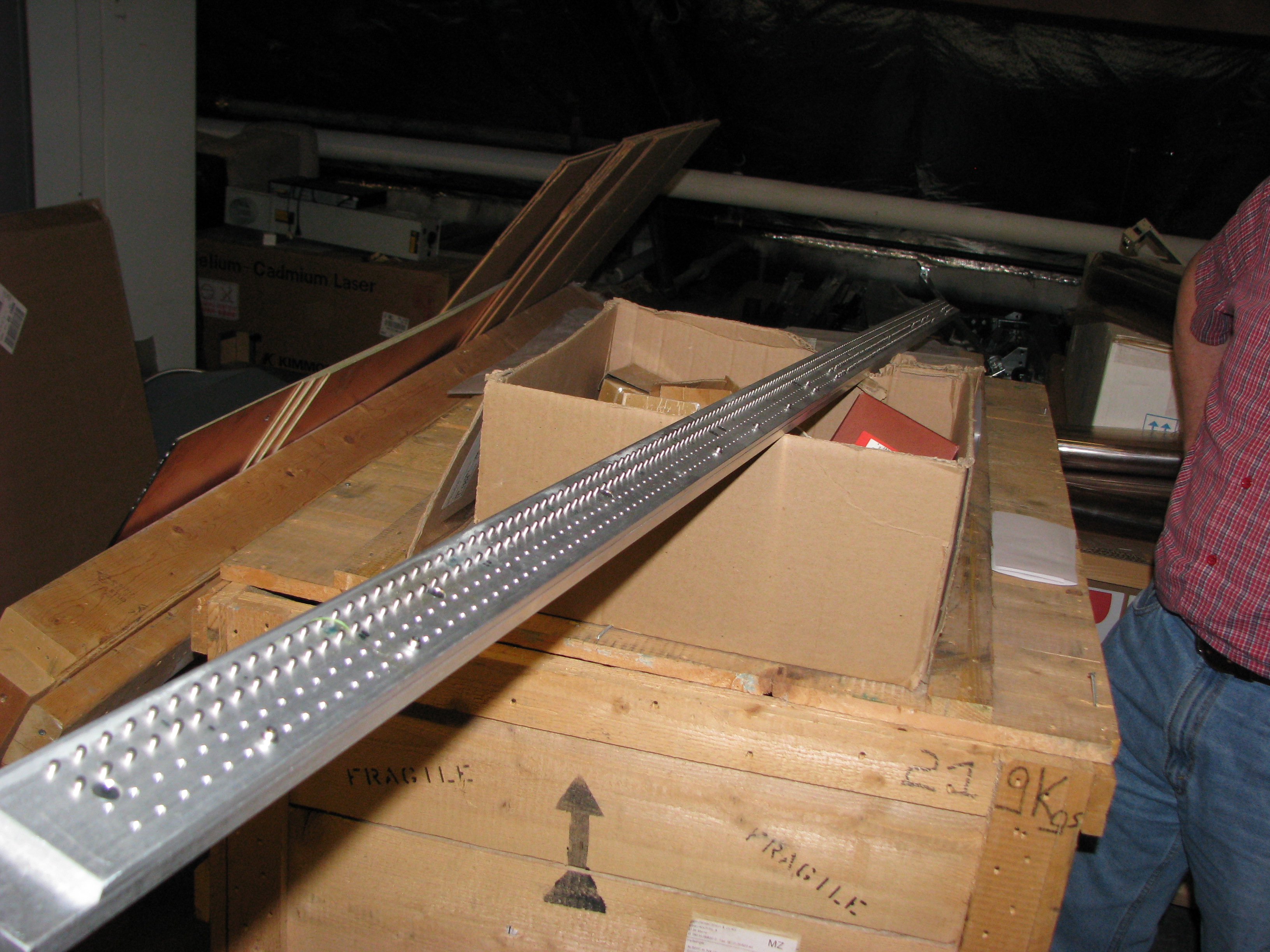
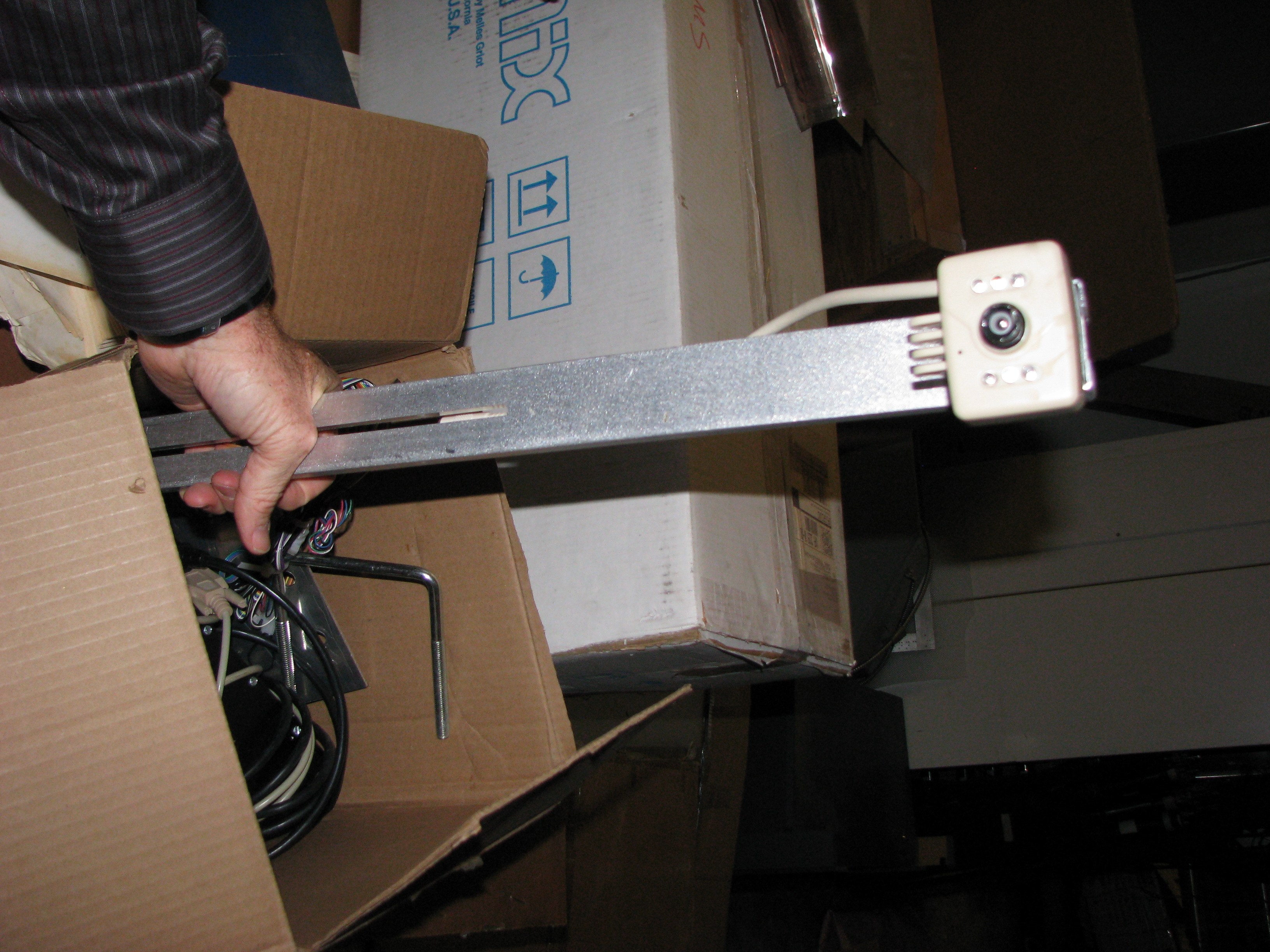
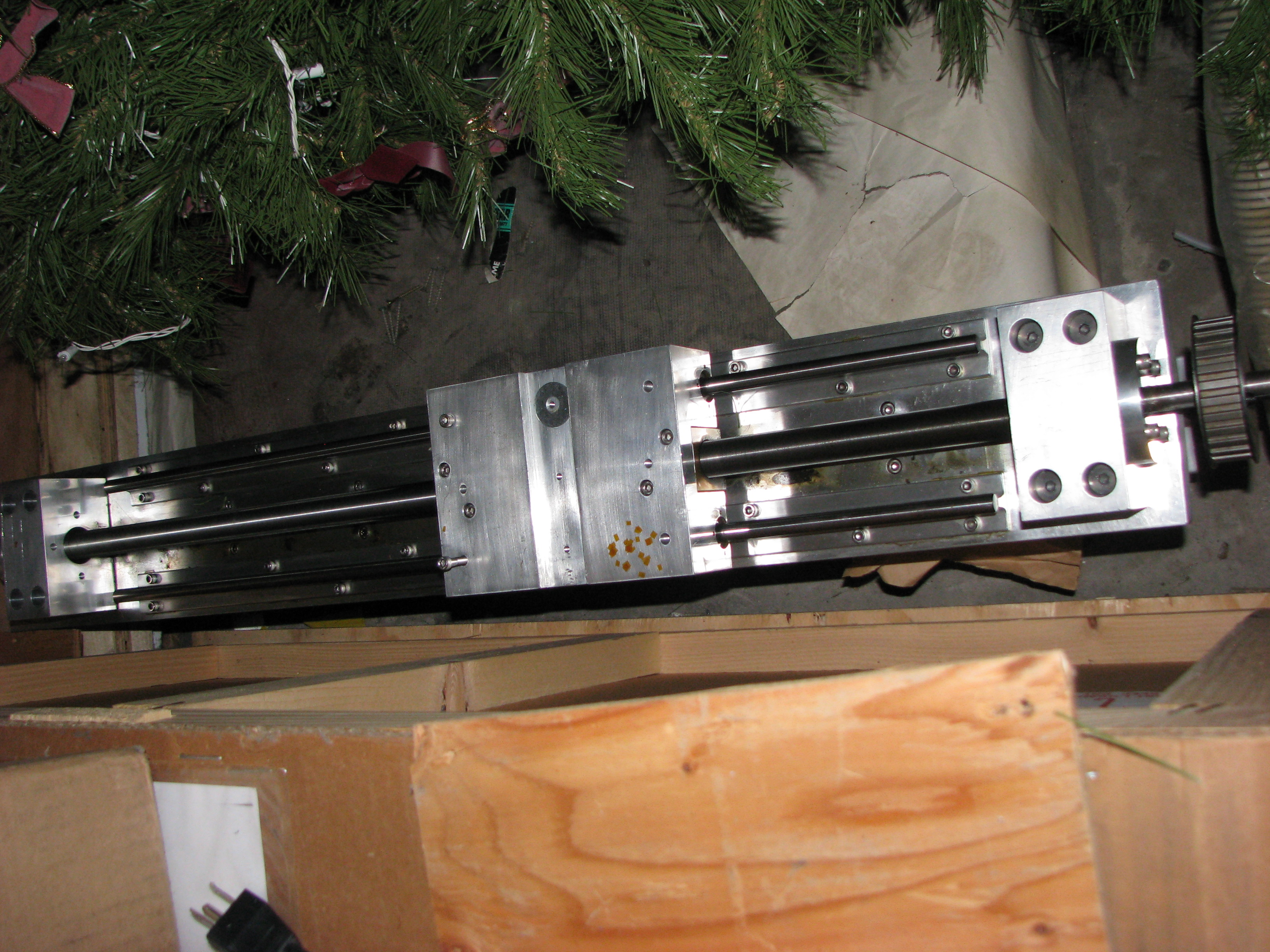
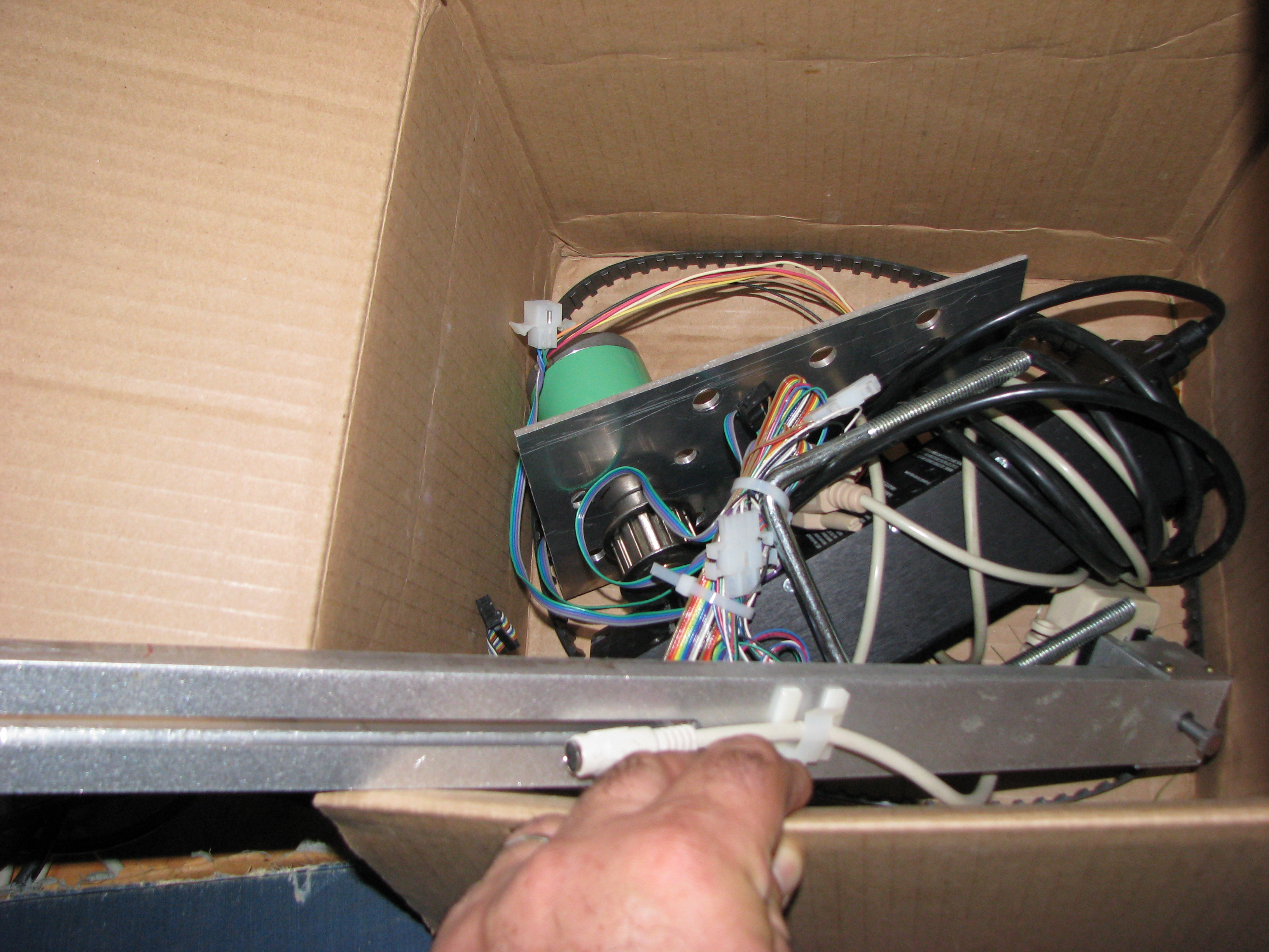
- plans for wire stringing in 126 pin rail, pos meas cam, pos meas , pos meas parts, pretension screw, string table
- Electronics
- fADC125 status (Gerard, Fernando)
- ground modifications
- Cathode redesign: finalizing (Roger, Bill)
- Full-scale prototype tests
- tests with fADC FDC Log Book, pages 494 - 500 (Lubomir)
- cosmic tests (Beni)
- Other
Minutes
Participants: Bill, Glenn, Casey, Roger, Mark, Fernando, Beni, Simon, and Lubomir.
Production
- Bill: the PR for the clean room is in place but not for the ACs. We will need the AC, the one for the whole bay area, to start moving there some stuff and do some dirty work that doesn't require clean environment. Teresa Danforth is the person to be contacted and Glenn will help us in that.
- Bill: the cathode production plan is in a good shape: Fast Track procedure will be posted soon. The wire production planing will require more information since we have not done the stringing. Therefore, first we need to start setting up the fixtures from UVA and exercising and then clarify the procedure.
- We will start setting up the stringing in the tent in 126. The other option, F117, is no longer an option since there's not enough space. We decided to use the granite table in 126 for stringing. We are going to put wheels on that table. For the cathode production we will need another two granite tables. Lubomir: According to Eugene there are money for equipment so that we can buy two granite table right now. Glenn confirmed that and said that he could sign for Eugene, who is away from JLab till July 7. The plan is to put the tables directly in 727 B.C.
Electronics
- fADC125: Lubomir did further studies of the cutoff seen in the spectra from the wires. As suggested by Gerard on the last meeting now a quadratic interpolation is used to find the maximum from the fADC samples. At page 498 in the FDC logbook, shown are the maximum signal distributions separately for all the channels. The cutoff position varies from channel to channel somehow and probably this is the reason we don't see a good peak at the saturation region. Fernando asked if there's a peak in the spectra for the individual channels. Lubomir: there's not enough statistics to see clearly the peaks channel by channel. Lubomir will use the new scope and the differential probe to histogram the signals from the card directly and see if there's a saturation.
- Bill proposed a modification of the cathode production procedure: cutting the foil from the transfer ring will be done not at the I.D. position but at a larger (by an inch) radius. This will allow to flap the copper foil over the whole periphery of the cathode ring to improve the grounding connections. Thus, no modifications of the cathode g10 ring are needed. The back of the cards will be glued on the copper foil with conductive epoxy. The aluminum ground foil will be glued at one side to the cathode copper foil and Bill proposed to use conductive ink to connect the other side of the aluminum foil to the cathode. Fernando: conductive ink may not be the right choice