Difference between revisions of "Minutes-7-15-2010"
(→Full-scale prototype test results) |
|||
| (14 intermediate revisions by the same user not shown) | |||
| Line 16: | Line 16: | ||
#* oxygen contamination measurements [http://www.jlab.org/Hall-D/software/wiki/index.php/Image:Halld_gas_systemB_v2.gif Beni's scheme] | #* oxygen contamination measurements [http://www.jlab.org/Hall-D/software/wiki/index.php/Image:Halld_gas_systemB_v2.gif Beni's scheme] | ||
# Other | # Other | ||
| − | |||
| − | |||
= Minutes = | = Minutes = | ||
| − | Participants: Fernando, | + | Participants: Eugene, Fernando, Glenn, Roger, Mark, Casey, Beni, Simon, and Lubomir. |
| − | + | ||
== Production == | == Production == | ||
| − | - | + | - The PR for the clean room is signed and out for bid. Ron Bartek is working on the HVAC, estimating to have it by early September. For our planning we assume we will have the clean room at the beginning of October. |
| − | - | + | - Lubomir included in the Fast Track file the production of the one-layer prototype which will take 2.5 weeks if having 8 technicians. This includes one wire and two cathode layers. Suppose we start on Oct.4 we will be ready with the prototype on Oct.20. Then, we can start with the mass production at the beginning of November. This answers Fernando's questions when we will need the PCBs. Fernando also asked if we have the 8 technicians needed for the job. Eugene answered, we would have to hire new techs. It will be difficult because the term will be only for one year, but probably we will need some of them for the constructions in the hall, as well. This will be synchronized later when it will be clear when we will have the clean room. |
| − | the | + | |
| − | + | ||
| − | + | ||
| − | + | ||
| − | + | ||
| − | + | ||
| − | + | ||
| − | + | ||
| − | + | ||
| − | + | ||
| − | + | ||
| − | + | ||
| − | + | ||
| − | + | ||
| − | + | ||
| − | + | ||
| − | + | ||
| − | the | + | |
| − | + | ||
| − | + | ||
| − | - Bill | + | - No news from Bill about the design of the wire stringing fixtures. He wanted to use the strongbacks that are at IUCF: Lubomir tried to contact Keith Solberg from IUCF, without success so far. In this line, the system for wire position measurements was recovered at UVA, they are testing it right now at UVA. We will have to find a way to bring it here. |
| − | + | They plan also to improve their system for tension measurements, based on exciting the wires by induction from an electrode and looking for the resonance frequency. Glenn suggested to talk to Mac Mestayer from Hall B about their system. Fernando said that the problem with the Hall B system is that you need to make connections to both ends of the wire. In our case this will be difficult especially for the field wires. | |
| − | right | + | |
| − | + | ||
| − | + | ||
| − | - | + | - The templates for the rohacell arcs are ready. The two Liping's students that were supposed to work on this project are working in the moment on the PRIMEX experiment. However, Lubomir talked to Ashot: we may use the students when they are not busy, will be discussed again tomorrow. We will need also a gluing template, Bill will get it made by the machine shop. |
| − | + | ||
| − | + | ||
== Electronics == | == Electronics == | ||
| − | - Fernando: | + | - Fernando: we expect the first PCBs next week. It turned out that the HV capacitors (rated for 4kV) are not available in the moment, and there's a lead time of 12 weeks if we want to order them. Instead there are 3kV capacitors available. Fernando asked if this is acceptable. Eugene mentioned the problems with the FCAL capacitors and asked if we can wait for the original capacitors that were used already in the prototype. Fernando: we will need the capacitors in August to proceed with the stuffing of the PCBs; 3kV and 4kV capacitors are really the same type (different from the FCAL ones) just rated for different HV. We don't expect to put HV more than 3kV for sure. Eugene suggested to do extensive tests of the 3kV capacitors at the working HV. |
| − | + | ||
| − | + | ||
| − | + | ||
| − | + | ||
| − | + | ||
| − | + | ||
| − | + | ||
| − | the | + | |
| + | == Engineering == | ||
| − | + | - Cathode foils: Roger showed us a plastic cylinder and a paper sample he received from the company to be used for transporting the foils. Mark said this paper should work (he had bad experience before with a sticky on one side paper). Fernando and Glenn suggested possible improvements: placing caps on the cylinder ends, using two cylinders with the foil in between. There are also other questions that need to be iterated with the company, like how many foils will be rolled on one cylinder. Roger will further communicate with the company to improve the packaging, while Mark and Casey will exercise packing using the company's paper. Roger is also checking the Gerber files and will send them soon to the company for quotation. | |
| − | - | + | - We have now two (one of each type) new design cathode frames machined in our machine shop. There was a problem with the vacuum fixture during the machining of one of the frames. According to Bill the procedure will change and this will not reoccur. Mark and Casey will prototype the new flapping design (to improve the grounding), using the foils that we have now. Roger will give them drawings to cut the flaps according to the new design. Mark and Casey will also improve the procedure of gluing the foil to the transfer ring so that there's extra length to be used for the flaps. |
| − | + | ||
| − | + | ||
| − | + | ||
== Full-scale prototype test results == | == Full-scale prototype test results == | ||
| − | - | + | - Beni explained the procedure he used to calculate the wire resolution. The top two wire planes are read out, which wires are parallel. He plots the difference of the distances calculated from the drift times of the two layers as a function of the angle alpha (a drawing explaining this is attached above). He extracts the resolution for angles close to zero and gets about 200microns. The resolution is getting better if applying angle corrections. There's still a dependence of the corrected difference on the angle. Possible explanation: the time to distance relation used was for the standard field/sense voltages and now we have zero voltage on the field wires (otherwise it trips). |
| − | + | ||
| − | + | ||
| − | + | ||
| − | + | ||
| − | - | + | - Fernando asked if we are happy with the present gain and dynamic range of the pre-amps. Lubomir: in principle we can adjust the HV to correspond to the dynamic range of the cards |
| − | + | but it affects also the resolution. Now we have the gain at the cathode cards of 2.6mV/fC which is the lowest value in the cathode gain range. It would be better to have also lower gains (like 2.3) possible. Part of the problem about choosing the working HV is that we suspect we have oxygen contamination that reduces the amplitude: up to factor of two effect for the longest drift distances. If this is the case, without contamination we could lower the HV by ~100V and have much narrower dynamic range. | |
| − | also | + | |
| − | + | ||
| − | + | ||
| − | -- | + | - We still don't have all the hardware needed to set-up the oxygen measurement system. First, Casey and Mark will install wheels on the rack. Beni is still waiting for the flow controller. |
Latest revision as of 23:05, 15 July 2010
July 15, 2010 FDC meeting
Contents
Tentative Agenda
- Production
- 727 B.C. status
- production planning
- wire stringing design
- rohacell ring production
- Electronics: update (Fernando)
- Engineering
- Cathode foil: update (Roger)
- Cathode frame prototyping
- Full-scale prototype tests
- cosmic test results (Beni) FDC Log Book, pages 505
- oxygen contamination measurements Beni's scheme
- Other
Minutes
Participants: Eugene, Fernando, Glenn, Roger, Mark, Casey, Beni, Simon, and Lubomir.
Production
- The PR for the clean room is signed and out for bid. Ron Bartek is working on the HVAC, estimating to have it by early September. For our planning we assume we will have the clean room at the beginning of October.
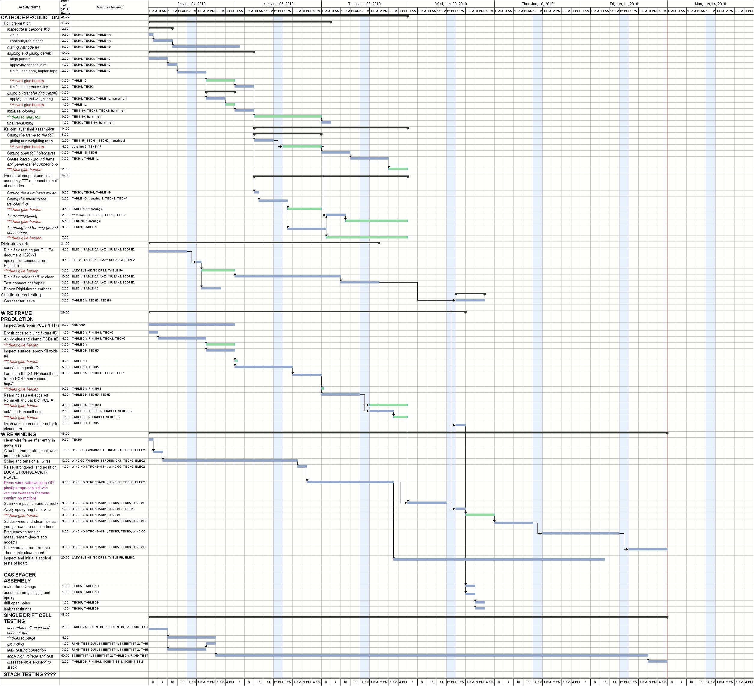
- Lubomir included in the Fast Track file the production of the one-layer prototype which will take 2.5 weeks if having 8 technicians. This includes one wire and two cathode layers. Suppose we start on Oct.4 we will be ready with the prototype on Oct.20. Then, we can start with the mass production at the beginning of November. This answers Fernando's questions when we will need the PCBs. Fernando also asked if we have the 8 technicians needed for the job. Eugene answered, we would have to hire new techs. It will be difficult because the term will be only for one year, but probably we will need some of them for the constructions in the hall, as well. This will be synchronized later when it will be clear when we will have the clean room.
- No news from Bill about the design of the wire stringing fixtures. He wanted to use the strongbacks that are at IUCF: Lubomir tried to contact Keith Solberg from IUCF, without success so far. In this line, the system for wire position measurements was recovered at UVA, they are testing it right now at UVA. We will have to find a way to bring it here. They plan also to improve their system for tension measurements, based on exciting the wires by induction from an electrode and looking for the resonance frequency. Glenn suggested to talk to Mac Mestayer from Hall B about their system. Fernando said that the problem with the Hall B system is that you need to make connections to both ends of the wire. In our case this will be difficult especially for the field wires.
- The templates for the rohacell arcs are ready. The two Liping's students that were supposed to work on this project are working in the moment on the PRIMEX experiment. However, Lubomir talked to Ashot: we may use the students when they are not busy, will be discussed again tomorrow. We will need also a gluing template, Bill will get it made by the machine shop.
Electronics
- Fernando: we expect the first PCBs next week. It turned out that the HV capacitors (rated for 4kV) are not available in the moment, and there's a lead time of 12 weeks if we want to order them. Instead there are 3kV capacitors available. Fernando asked if this is acceptable. Eugene mentioned the problems with the FCAL capacitors and asked if we can wait for the original capacitors that were used already in the prototype. Fernando: we will need the capacitors in August to proceed with the stuffing of the PCBs; 3kV and 4kV capacitors are really the same type (different from the FCAL ones) just rated for different HV. We don't expect to put HV more than 3kV for sure. Eugene suggested to do extensive tests of the 3kV capacitors at the working HV.
Engineering
- Cathode foils: Roger showed us a plastic cylinder and a paper sample he received from the company to be used for transporting the foils. Mark said this paper should work (he had bad experience before with a sticky on one side paper). Fernando and Glenn suggested possible improvements: placing caps on the cylinder ends, using two cylinders with the foil in between. There are also other questions that need to be iterated with the company, like how many foils will be rolled on one cylinder. Roger will further communicate with the company to improve the packaging, while Mark and Casey will exercise packing using the company's paper. Roger is also checking the Gerber files and will send them soon to the company for quotation.
- We have now two (one of each type) new design cathode frames machined in our machine shop. There was a problem with the vacuum fixture during the machining of one of the frames. According to Bill the procedure will change and this will not reoccur. Mark and Casey will prototype the new flapping design (to improve the grounding), using the foils that we have now. Roger will give them drawings to cut the flaps according to the new design. Mark and Casey will also improve the procedure of gluing the foil to the transfer ring so that there's extra length to be used for the flaps.
Full-scale prototype test results
- Beni explained the procedure he used to calculate the wire resolution. The top two wire planes are read out, which wires are parallel. He plots the difference of the distances calculated from the drift times of the two layers as a function of the angle alpha (a drawing explaining this is attached above). He extracts the resolution for angles close to zero and gets about 200microns. The resolution is getting better if applying angle corrections. There's still a dependence of the corrected difference on the angle. Possible explanation: the time to distance relation used was for the standard field/sense voltages and now we have zero voltage on the field wires (otherwise it trips).
- Fernando asked if we are happy with the present gain and dynamic range of the pre-amps. Lubomir: in principle we can adjust the HV to correspond to the dynamic range of the cards but it affects also the resolution. Now we have the gain at the cathode cards of 2.6mV/fC which is the lowest value in the cathode gain range. It would be better to have also lower gains (like 2.3) possible. Part of the problem about choosing the working HV is that we suspect we have oxygen contamination that reduces the amplitude: up to factor of two effect for the longest drift distances. If this is the case, without contamination we could lower the HV by ~100V and have much narrower dynamic range.
- We still don't have all the hardware needed to set-up the oxygen measurement system. First, Casey and Mark will install wheels on the rack. Beni is still waiting for the flow controller.