Difference between revisions of "Minutes-7-29-2010"
| Line 19: | Line 19: | ||
# Other | # Other | ||
| − | + | ||
= Minutes = | = Minutes = | ||
| − | Participants: Eugene | + | Participants: Eugene, Fernando, Glenn, Roger, Casey, Mark, Bill, Beni, Simon, Vladimir Nelyubin, and Lubomir. |
| − | |||
| − | |||
| − | |||
== Production == | == Production == | ||
| Line 32: | Line 29: | ||
- No news about Blue Crab. | - No news about Blue Crab. | ||
| − | - | + | - There will be a meeting, end of next week, including Tim and Tom about the FDC production and the tech labor. Bill prefers to start the production with 5 techs and then based on the performance, to adjust this number to have the chambers produced in time. Eugene suggested 20% contingency. According to the baseline the production should start in November 2010 and finish in October 2012, including the testing. The installation starts in January 2013. |
== Electronics == | == Electronics == | ||
| − | - Fernando: | + | - Fernando: received the first article PCBs but has not looked yet; still waiting for F117 to be ready for use. Mark is helping in making space there. Fernando will test the boards by himself, including mechanical tests. If they pass, CEM will continue with the full production, then all the boards together will be send for stuffing. |
| − | - | + | - two vendors responded for the 18m cable assembly. If they both meet the requirements, the lower price criteria will apply. Bill was concerned about the length of the part of the cable on which the ground is removed. Fernando: that length is equal to the distance from the front of the magnet to the FDC package, there's no big change in the diameter of the cable, so it shouldn't be a problem to feed the cables between CDC and BCAL if taking the FDC upstreams for maintenance. No news about fADC. |
| − | + | ||
| − | + | ||
== Engineering == | == Engineering == | ||
| − | - Cathode foils: Roger | + | - Cathode foils: we discussed Roger's PR for the cathode foils. Next week he will generate a sole-source PR. One set of panels will be packed in one tube. We discussed some procurement related issues, like small businesses, priority. The cathode foil PR will have 1st priority, Bill will change the priorities for the wire and cathode frames from 3 to 1. |
| + | |||
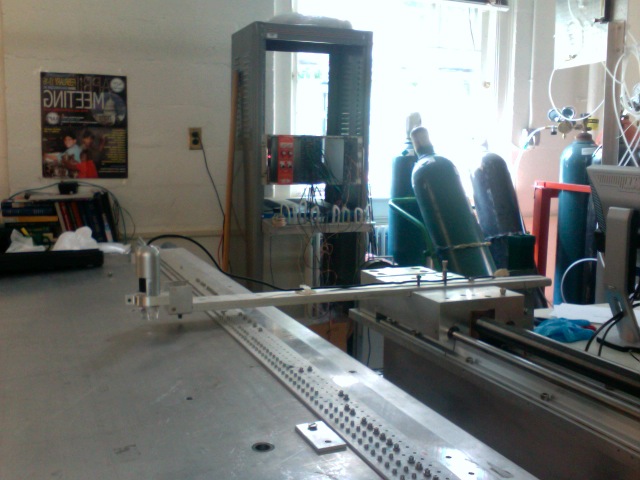
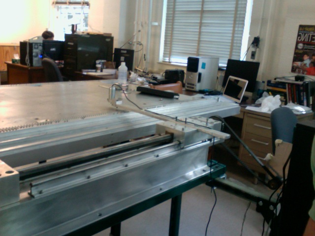
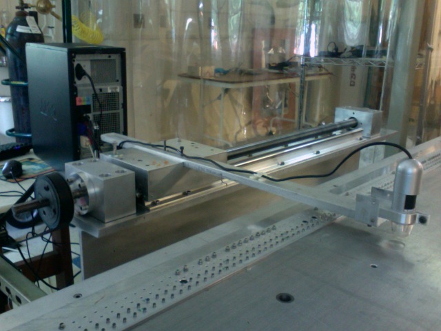
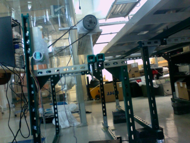
| + | - Wire stringing: Bill had concerns about the precision of the position system at UVA (see pictures attached above). Vladimir explained how the system works and answered Bill's questions. They have measured the resolution to be 25 microns. Vladimir thinks it can be improved (as Bill suggested), but it is good enough for our purposes. Bill was concerned also about the space the system will occupy and that we have to move it around the table. Different options were discussed: moving the table, using two cameras. Bill: if he would start from scratch, he would build different system with better resolution. The plan is to get the system at JLab, check the resolution and then to decide what to do. Vladimir also explained how the tension measurement works: apply sine voltage on an electrode on the top of the chamber and pick up the signal from another electrode on the top of the wire to look for resonance. | ||
| − | - | + | - The next step withe the cathode frame prototyping would be to glue the flaps on the back of the frame and then to glue the mylar foil which is now glued to the transfer ring. |
| − | - | + | == Full-scale prototype test == |
| − | + | ||
| − | + | ||
| − | - | + | - Lubomir studied with Garfield the drift velocities and the magnetic field effects for different gas mixtures: 90/10, 70/30 and 40/60% Ar/CO2 (see pictures attached). 90/10 is the best from velocity point of view, since it is almost constant with respect to the electric field, while 40/60 exhibits strong dependence. As for the Lorentz angle, it is a factor of two bigger for 90/10 than for 40/60 and hence the deflection of the trajectories due the magnetic field will be bigger. The effect of these two factors on the drift time resolution are demonstrated at page 507 of the FDC logbook: plotted are the drift time spectra for the two gas mixtures with and without magnetic field. The resolutions are better for 90/10 even the increase of the drift time is much bigger for 90/10 compared to 40/60. Simon: we should consider also the shift in the position along the wire. Eugene: we might benefit from bigger shifts when solving left/right ambiguity. There's also the question of stability of operation with less quenching. Beni will switch to 90/10 mixture at the end of the week. Lubomir also studied the effect of the field wire voltage. The best drift time resolution is achieved with the field wires at zero voltage, in which case there are no filed lines between the field wires and the cathode and the field is more cylindrically symmetric which results in better resolution. |
| − | + | - Beni is working with the bottom layer: same high efficiency, hasn't studied yet the top/bottom asymmetry we observed for the top and middle layers. Beni si varying now the field potential and after that he will switch to 90/10 gas mixture. | |
| − | - Beni | + | - Beni set up the oxygen measuring system, first using the old oxygen sensor. The readings were controversial and now he is acquiring the parts needed to connect the new oxygen sensor. |
| − | + | == Other == | |
| − | + | At the end Vladimir suggested to use the milling machine system (with 1mil=25 microns accuracy) in the machine shop to check the UVA position measuring system. | |
Revision as of 18:24, 29 July 2010
July 29, 2010 FDC meeting
Contents
Tentative Agenda
- Production
- 727 B.C. status
- production planing status 5 techs production schedule
- Electronics (Fernando)
- new PCB tests
- other updates: cable procurement, fADC
- Engineering
- Full-scale prototype tests
- discussions about gas mixture and field configuration (Lubomir) FDC Log Book, pages 507-508
- cosmic test update (Beni)
- oxygen contamination measurements (Beni) Beni's scheme
- Other
Minutes
Participants: Eugene, Fernando, Glenn, Roger, Casey, Mark, Bill, Beni, Simon, Vladimir Nelyubin, and Lubomir.
Production
- No news about Blue Crab.
- There will be a meeting, end of next week, including Tim and Tom about the FDC production and the tech labor. Bill prefers to start the production with 5 techs and then based on the performance, to adjust this number to have the chambers produced in time. Eugene suggested 20% contingency. According to the baseline the production should start in November 2010 and finish in October 2012, including the testing. The installation starts in January 2013.
Electronics
- Fernando: received the first article PCBs but has not looked yet; still waiting for F117 to be ready for use. Mark is helping in making space there. Fernando will test the boards by himself, including mechanical tests. If they pass, CEM will continue with the full production, then all the boards together will be send for stuffing.
- two vendors responded for the 18m cable assembly. If they both meet the requirements, the lower price criteria will apply. Bill was concerned about the length of the part of the cable on which the ground is removed. Fernando: that length is equal to the distance from the front of the magnet to the FDC package, there's no big change in the diameter of the cable, so it shouldn't be a problem to feed the cables between CDC and BCAL if taking the FDC upstreams for maintenance. No news about fADC.
Engineering
- Cathode foils: we discussed Roger's PR for the cathode foils. Next week he will generate a sole-source PR. One set of panels will be packed in one tube. We discussed some procurement related issues, like small businesses, priority. The cathode foil PR will have 1st priority, Bill will change the priorities for the wire and cathode frames from 3 to 1.
- Wire stringing: Bill had concerns about the precision of the position system at UVA (see pictures attached above). Vladimir explained how the system works and answered Bill's questions. They have measured the resolution to be 25 microns. Vladimir thinks it can be improved (as Bill suggested), but it is good enough for our purposes. Bill was concerned also about the space the system will occupy and that we have to move it around the table. Different options were discussed: moving the table, using two cameras. Bill: if he would start from scratch, he would build different system with better resolution. The plan is to get the system at JLab, check the resolution and then to decide what to do. Vladimir also explained how the tension measurement works: apply sine voltage on an electrode on the top of the chamber and pick up the signal from another electrode on the top of the wire to look for resonance.
- The next step withe the cathode frame prototyping would be to glue the flaps on the back of the frame and then to glue the mylar foil which is now glued to the transfer ring.
Full-scale prototype test
- Lubomir studied with Garfield the drift velocities and the magnetic field effects for different gas mixtures: 90/10, 70/30 and 40/60% Ar/CO2 (see pictures attached). 90/10 is the best from velocity point of view, since it is almost constant with respect to the electric field, while 40/60 exhibits strong dependence. As for the Lorentz angle, it is a factor of two bigger for 90/10 than for 40/60 and hence the deflection of the trajectories due the magnetic field will be bigger. The effect of these two factors on the drift time resolution are demonstrated at page 507 of the FDC logbook: plotted are the drift time spectra for the two gas mixtures with and without magnetic field. The resolutions are better for 90/10 even the increase of the drift time is much bigger for 90/10 compared to 40/60. Simon: we should consider also the shift in the position along the wire. Eugene: we might benefit from bigger shifts when solving left/right ambiguity. There's also the question of stability of operation with less quenching. Beni will switch to 90/10 mixture at the end of the week. Lubomir also studied the effect of the field wire voltage. The best drift time resolution is achieved with the field wires at zero voltage, in which case there are no filed lines between the field wires and the cathode and the field is more cylindrically symmetric which results in better resolution.
- Beni is working with the bottom layer: same high efficiency, hasn't studied yet the top/bottom asymmetry we observed for the top and middle layers. Beni si varying now the field potential and after that he will switch to 90/10 gas mixture.
- Beni set up the oxygen measuring system, first using the old oxygen sensor. The readings were controversial and now he is acquiring the parts needed to connect the new oxygen sensor.
Other
At the end Vladimir suggested to use the milling machine system (with 1mil=25 microns accuracy) in the machine shop to check the UVA position measuring system.