Difference between revisions of "Minutes-7-8-2010"
(→Full-scale prototype test results) |
|||
| (11 intermediate revisions by the same user not shown) | |||
| Line 14: | Line 14: | ||
#* oxygen contamination measurements [http://www.jlab.org/Hall-D/software/wiki/index.php/Image:Halld_gas_systemB_v2.gif Beni's scheme] | #* oxygen contamination measurements [http://www.jlab.org/Hall-D/software/wiki/index.php/Image:Halld_gas_systemB_v2.gif Beni's scheme] | ||
# Other | # Other | ||
| − | |||
| − | |||
= Minutes = | = Minutes = | ||
| − | Participants: Bill, Roger, Mark | + | Participants: Fernando, Bill, Roger, Mark, Bob, and Lubomir (fewer people |
| + | because of the trigger meeting at CNU at the same time). | ||
| − | + | == Production == | |
| − | + | - According to Tim, the PR for the clean room is awaiting Claus Rode's signature. | |
| − | - Bill | + | - Long discussion about the production procedures. Bill included in the Fast Track also the wire frame production, the wire stringing, and the testing of |
| + | the chamber layers. The file is linked above (as jpeg) and is open for | ||
| + | discussions and improvements. Bill asked Mark to look at the file (with Fast | ||
| + | Track from Tom) and give his comments. 8 technicians will be involved full day | ||
| + | and will produce one layer for 6 days, but realistically we assume 8 days. For | ||
| + | 30 layers it will be 240 working days. In addition, two scientists will | ||
| + | assemble the stack and do HV and cosmics tests. The exact tests are not yet | ||
| + | defined, but the idea is to use all the time available for such tests, but not | ||
| + | more than needed for the layer production. Fernando asked about the cleaning | ||
| + | of the wire frames after soldering and we discussed different options for | ||
| + | ultrasonic cleaning. Fernando wanted to have a flow chart of the production | ||
| + | with dates, so that he knows when the different components are needed for the | ||
| + | production. One of the main unknown is when realistically we can move to the | ||
| + | off-site space and start organizing the production. The plan is to have the | ||
| + | wire frames by 8/24 (first article) and 9/20 (all 30). According to Fernando | ||
| + | we will have the PCBs by 7/19 (first article) and by 8/19 (all). The PR for | ||
| + | the cathode foils will be submitted next week and the timing of their | ||
| + | production is not known yet, but Roger has contacted the company: they can do | ||
| + | the first article by the middle of August (assuming the procurement doesn't | ||
| + | take a lot of time). Using this information, Lubomir will start working on the | ||
| + | flow chart with dates on it. | ||
| − | - Bill | + | - Bill explained us his ideas about the wire stringing. He will use the strong-back that is at IUCF. Lubomir will take care of bringing the |
| + | strong-back to JLab. The idea is to use tape pads to hold the wires at the | ||
| + | right positions before gluing and soldering them. The wire positions will | ||
| + | adjusted by hands (or with some tool) using the camera. We discussed once more | ||
| + | different options for the tension measurements. | ||
| − | - | + | - the templates for the rohacell arcs will be ready next Wednesday. Two students will start cutting the arcs, supervised by Mark. Bill said the most |
| + | important is to have the I.D. cut correctly. The arcs will be stored in a box | ||
| + | and then they will start gluing the rings. | ||
| − | == | + | == Electronics == |
| − | - | + | - Fernando: CEM was awarded to produce the PCBs. After getting the first article (two of each) on 7/19, the PCBs will be tested by Fernando within |
| − | + | two weeks before starting the mass production. In parallel, the first boards | |
| − | + | will be given to an outside company for stuffing, they will be tested again and | |
| + | then we will continue with the stuffing of all the boards. | ||
| − | - Lubomir | + | - Lubomir looked with the differential probe at the output (with 18m cable) of the new anode and cathode cards. The dynamic range of the anode cards is |
| + | about 2/3 of the range of the cathode cards; according to Fernando this is | ||
| + | normal and comes from the difference in the gains. This explains the cutoff in | ||
| + | the fADC spectra discussed before. | ||
| − | |||
| − | - | + | == Cathode redesign == |
| + | |||
| + | - Roger is ready with the design, except for a few cosmetic changes. He will send the Gerber files to the company by tomorrow and expects estimations | ||
| + | from the company for 70 cathodes by the middle of the next week. At the same | ||
| + | time he will start the PR paperwork, so that he can submit it as soon as he | ||
| + | gets the quotation from the company. | ||
| + | |||
| + | == Full-scale prototype test results == | ||
| + | |||
| + | - Lubomir showed several Beni's plots, linked above. Based on high statistics cosmic data, the mean ADC, measuring the total charge from the wires, goes | ||
| + | down with the drift time. Same was observed before for the maximum amplitude, | ||
| + | using the fADC data. This can be explained by ~0.1% oxygen contamination. Beni | ||
| + | also did measurements at different, by 20%, gas flow rates, but there's no | ||
| + | visible change in the results. | ||
| − | - | + | - To measure the oxygen contamination we need a pump at the end of the oxygen sensor, as discussed last time. The problem is that the pressure there should |
| + | not be less than 0.5 atm, according to the documentation of the sensor. Beni | ||
| + | also confirmed this talking to the company. We will look what are the | ||
| + | parameters of the pump that we have. We may need a relieve valve to keep the | ||
| + | pressure there above half atm. | ||
Latest revision as of 18:40, 8 July 2010
July 8, 2010 FDC meeting
Contents
Tentative Agenda
- Production
- 727 B.C. status
- wire frame production planning
- wire stringing design
- rohacell ring production
- Electronics: update (Fernando)
- Cathode redesign: finalizing (Roger)
- Full-scale prototype tests
- cosmic test results (Beni) FDC Log Book, pages 504
- oxygen contamination measurements Beni's scheme
- Other
Minutes
Participants: Fernando, Bill, Roger, Mark, Bob, and Lubomir (fewer people because of the trigger meeting at CNU at the same time).
Production
- According to Tim, the PR for the clean room is awaiting Claus Rode's signature.
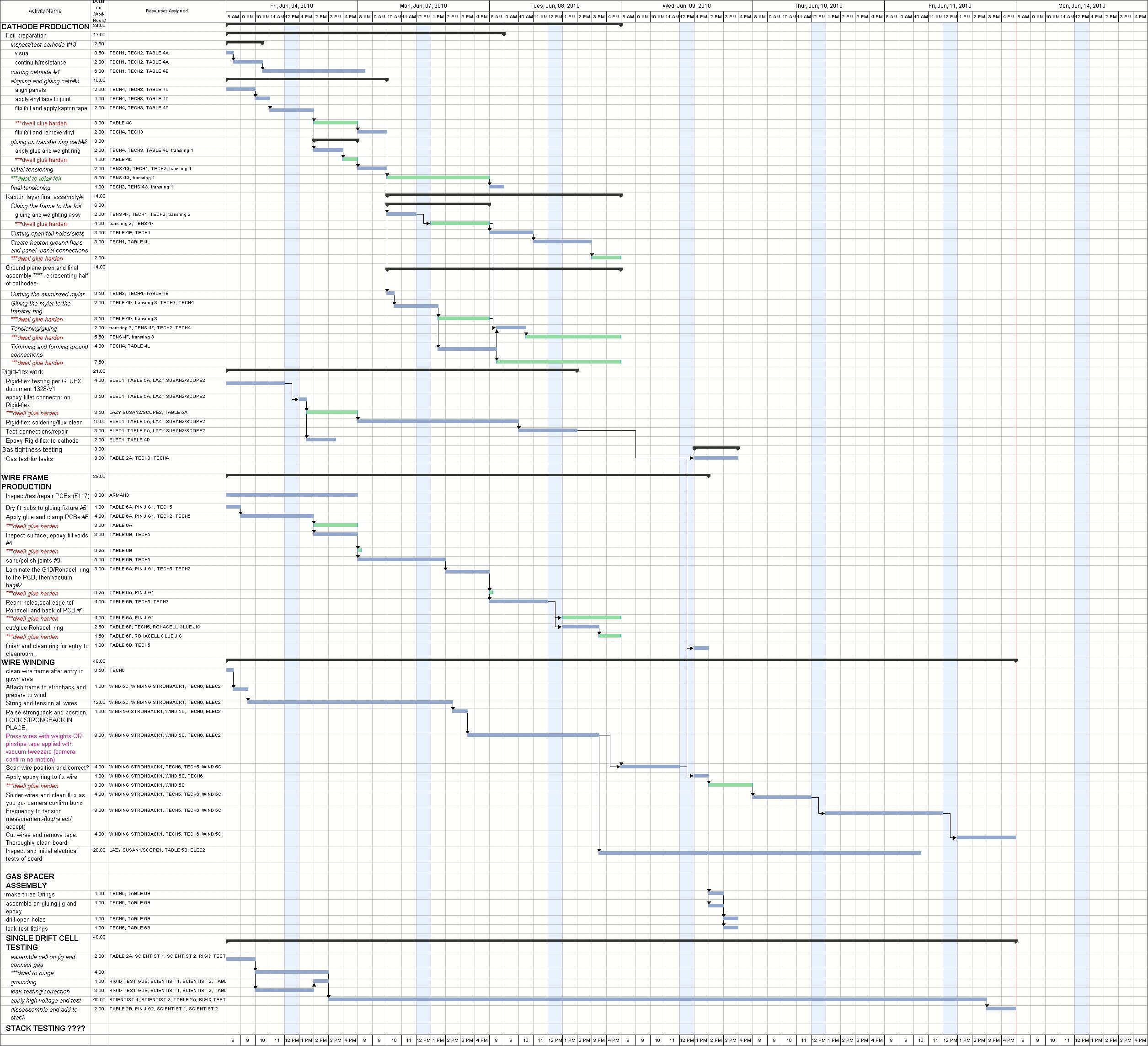
- Long discussion about the production procedures. Bill included in the Fast Track also the wire frame production, the wire stringing, and the testing of the chamber layers. The file is linked above (as jpeg) and is open for discussions and improvements. Bill asked Mark to look at the file (with Fast Track from Tom) and give his comments. 8 technicians will be involved full day and will produce one layer for 6 days, but realistically we assume 8 days. For 30 layers it will be 240 working days. In addition, two scientists will assemble the stack and do HV and cosmics tests. The exact tests are not yet defined, but the idea is to use all the time available for such tests, but not more than needed for the layer production. Fernando asked about the cleaning of the wire frames after soldering and we discussed different options for ultrasonic cleaning. Fernando wanted to have a flow chart of the production with dates, so that he knows when the different components are needed for the production. One of the main unknown is when realistically we can move to the off-site space and start organizing the production. The plan is to have the wire frames by 8/24 (first article) and 9/20 (all 30). According to Fernando we will have the PCBs by 7/19 (first article) and by 8/19 (all). The PR for the cathode foils will be submitted next week and the timing of their production is not known yet, but Roger has contacted the company: they can do the first article by the middle of August (assuming the procurement doesn't take a lot of time). Using this information, Lubomir will start working on the flow chart with dates on it.
- Bill explained us his ideas about the wire stringing. He will use the strong-back that is at IUCF. Lubomir will take care of bringing the strong-back to JLab. The idea is to use tape pads to hold the wires at the right positions before gluing and soldering them. The wire positions will adjusted by hands (or with some tool) using the camera. We discussed once more different options for the tension measurements.
- the templates for the rohacell arcs will be ready next Wednesday. Two students will start cutting the arcs, supervised by Mark. Bill said the most important is to have the I.D. cut correctly. The arcs will be stored in a box and then they will start gluing the rings.
Electronics
- Fernando: CEM was awarded to produce the PCBs. After getting the first article (two of each) on 7/19, the PCBs will be tested by Fernando within two weeks before starting the mass production. In parallel, the first boards will be given to an outside company for stuffing, they will be tested again and then we will continue with the stuffing of all the boards.
- Lubomir looked with the differential probe at the output (with 18m cable) of the new anode and cathode cards. The dynamic range of the anode cards is about 2/3 of the range of the cathode cards; according to Fernando this is normal and comes from the difference in the gains. This explains the cutoff in the fADC spectra discussed before.
Cathode redesign
- Roger is ready with the design, except for a few cosmetic changes. He will send the Gerber files to the company by tomorrow and expects estimations from the company for 70 cathodes by the middle of the next week. At the same time he will start the PR paperwork, so that he can submit it as soon as he gets the quotation from the company.
Full-scale prototype test results
- Lubomir showed several Beni's plots, linked above. Based on high statistics cosmic data, the mean ADC, measuring the total charge from the wires, goes down with the drift time. Same was observed before for the maximum amplitude, using the fADC data. This can be explained by ~0.1% oxygen contamination. Beni also did measurements at different, by 20%, gas flow rates, but there's no visible change in the results.
- To measure the oxygen contamination we need a pump at the end of the oxygen sensor, as discussed last time. The problem is that the pressure there should not be less than 0.5 atm, according to the documentation of the sensor. Beni also confirmed this talking to the company. We will look what are the parameters of the pump that we have. We may need a relieve valve to keep the pressure there above half atm.