Difference between revisions of "Parameterization of deflections/preliminary momentum resolution results"
| (10 intermediate revisions by the same user not shown) | |||
| Line 1: | Line 1: | ||
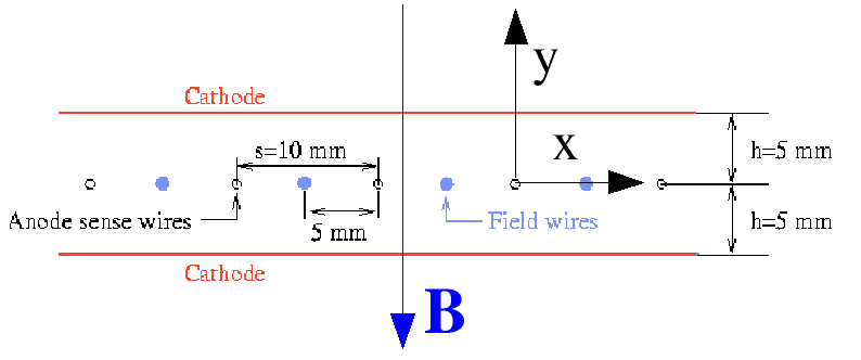
| − | Using the 1500 Amp TOSCA map provided by Paul Brindza, I ran Garfield calculations over a grid in z and r corresponding to the dimensions of the FDC to compute the deflections of the avalanches along the wire due to the Lorentz force. | + | Using the 1500 Amp TOSCA map provided by Paul Brindza, I ran Garfield calculations over a grid in z(along the beam) and r(-> x) corresponding to the dimensions of the FDC to compute the deflections of the avalanches along the wire due to the Lorentz force. The gas was 40% Argon/60% CO2. The Garfield coordinate system, shown below, is unfortunately not the same as the GlueX coordinate system. The deflections in the Garfield coordinate system are in the +/-z direction. This corresponds to deflections in the +/-y direction in the GlueX coordinate system. |
| − | + | ||
| − | [[Image: | + | [[Image:garf_coord.gif]] |
| − | The two slope (tangent) parameters describing the deflection planes are shown as a function of r and y | + | The behavior of this deflection for ionizations throughout a given FDC cell is well-described by a plane: |
| + | |||
| + | [[Image:deflection_example2.gif]] | ||
| + | |||
| + | The two slope (tangent) parameters describing the deflection planes are shown as a function of r and y(beam direction in GlueX coordinate system) here: | ||
[[Image:tan_def_angles.gif]] | [[Image:tan_def_angles.gif]] | ||
| + | |||
| + | Here r is the same as x in the GlueX coordinate system. For interactions in the FDC for other phi values, the tan(theta_y) component is | ||
| + | multiplied by cos(phi). | ||
The hitFDC.c routine in HDGeant has been modified to read in a table of these tangent values and interpolate the amount of deflection as a function of the | The hitFDC.c routine in HDGeant has been modified to read in a table of these tangent values and interpolate the amount of deflection as a function of the | ||
| − | point of closest approach to the avalanche wire on a wire-by-wire/event-by-event basis. | + | point of closest approach to the avalanche wire on a wire-by-wire/event-by-event basis. |
| + | |||
| + | Next I generated npi+ events with 9 GeV photon beam and t-slope of 0.25 GeV^-2 to mostly populate the forward region and ran the events through HDGeant. | ||
| + | One caveat is that the current version of the B-field in the repository has slightly less magnitude (~2T in the central region of the bore as compared | ||
| + | to ~2.2 T) than the one I used to generate the deflection table. Here is a comparison the momentum resolution as a function of theta for the case where | ||
| + | the deflection is turned on (red) vs the nominal case (black). No smearing was added. | ||
| + | |||
| + | [[Image:dp_p_v2.gif]] | ||
Latest revision as of 07:52, 23 May 2007
Using the 1500 Amp TOSCA map provided by Paul Brindza, I ran Garfield calculations over a grid in z(along the beam) and r(-> x) corresponding to the dimensions of the FDC to compute the deflections of the avalanches along the wire due to the Lorentz force. The gas was 40% Argon/60% CO2. The Garfield coordinate system, shown below, is unfortunately not the same as the GlueX coordinate system. The deflections in the Garfield coordinate system are in the +/-z direction. This corresponds to deflections in the +/-y direction in the GlueX coordinate system.
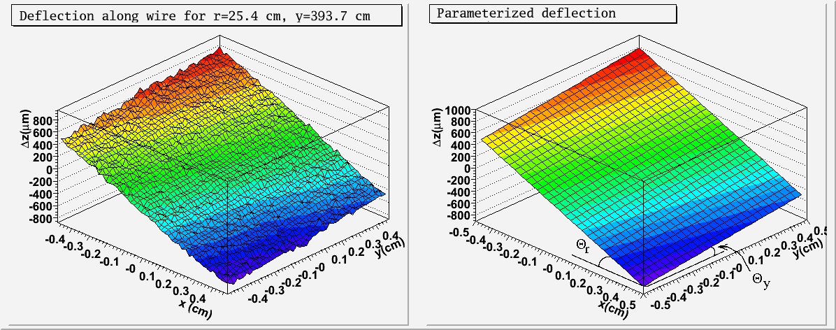
The behavior of this deflection for ionizations throughout a given FDC cell is well-described by a plane:
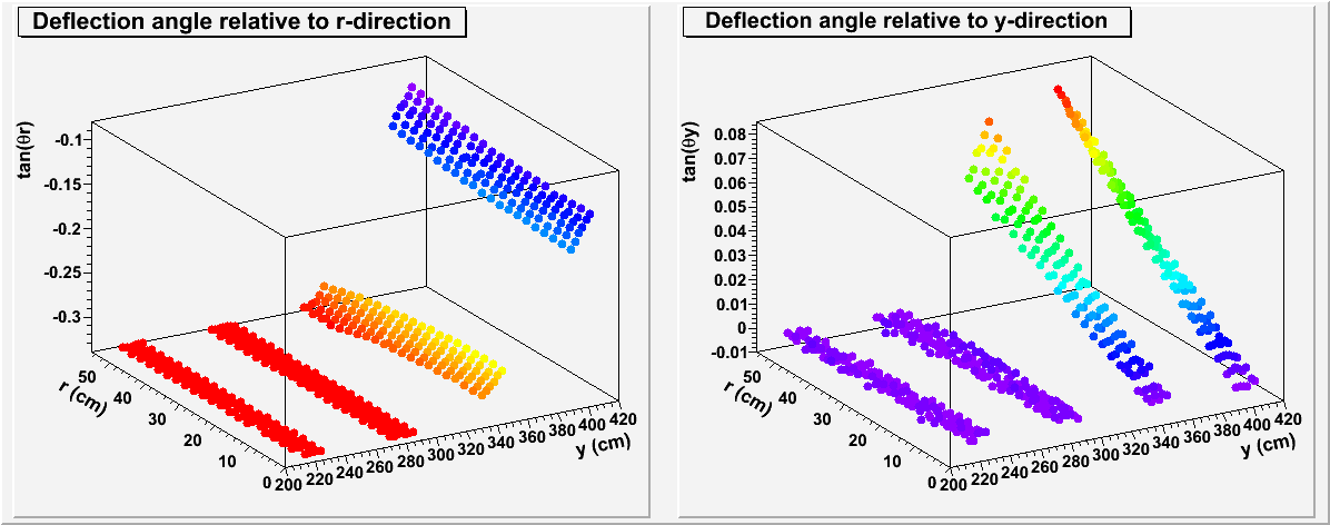
The two slope (tangent) parameters describing the deflection planes are shown as a function of r and y(beam direction in GlueX coordinate system) here:
Here r is the same as x in the GlueX coordinate system. For interactions in the FDC for other phi values, the tan(theta_y) component is multiplied by cos(phi).
The hitFDC.c routine in HDGeant has been modified to read in a table of these tangent values and interpolate the amount of deflection as a function of the point of closest approach to the avalanche wire on a wire-by-wire/event-by-event basis.
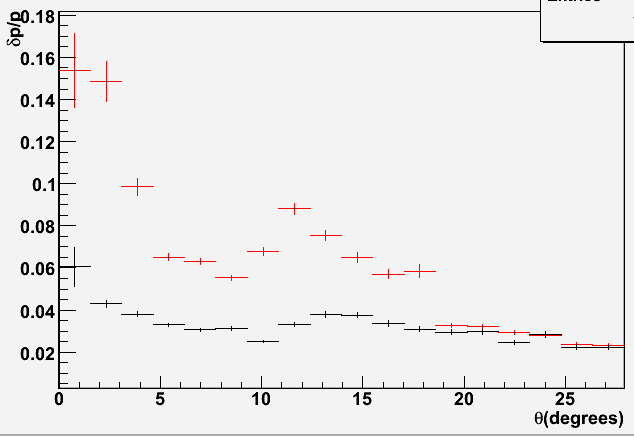
Next I generated npi+ events with 9 GeV photon beam and t-slope of 0.25 GeV^-2 to mostly populate the forward region and ran the events through HDGeant. One caveat is that the current version of the B-field in the repository has slightly less magnitude (~2T in the central region of the bore as compared to ~2.2 T) than the one I used to generate the deflection table. Here is a comparison the momentum resolution as a function of theta for the case where the deflection is turned on (red) vs the nominal case (black). No smearing was added.


