Difference between revisions of "Polarimeter 11 01 2010"
From GlueXWiki
(→Simulations) |
|||
| Line 39: | Line 39: | ||
* Some sort of detector made of silicon, 300μm thick. Consists of two pieces, left and right, for positrons and electrons. | * Some sort of detector made of silicon, 300μm thick. Consists of two pieces, left and right, for positrons and electrons. | ||
* The positions of the hit e<sup>+</sup> or e<sup>-</sup> hits are calculated as the energy-weighed average of individually hits within certain window. | * The positions of the hit e<sup>+</sup> or e<sup>-</sup> hits are calculated as the energy-weighed average of individually hits within certain window. | ||
| + | |||
| + | <br/> | ||
| + | |||
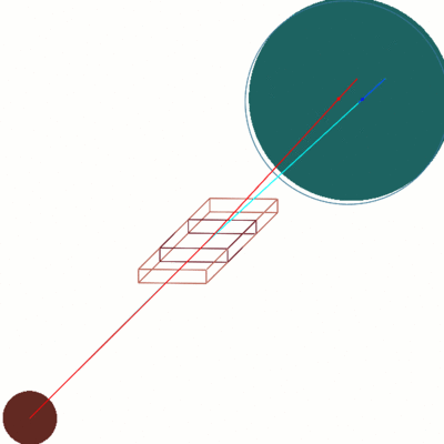
| + | [[Image:polarimeter_11_01_2010.gif|left|thumb|400px|A layout of the detector and the beamline for this simulations. ]] | ||
| + | |||
| + | <br/ clear="all"> | ||
| + | |||
| + | ---- | ||
| + | |||
| + | |||
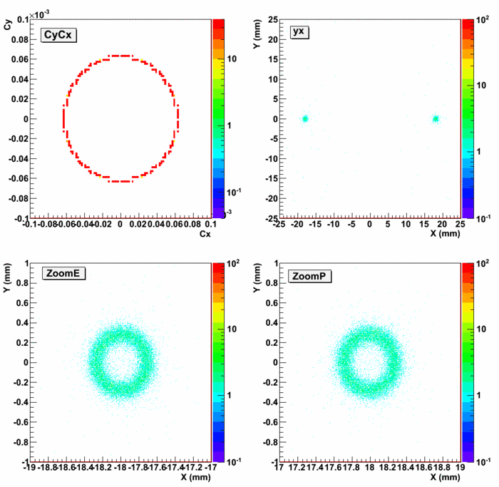
| + | [[Image:pairSym_20K_optim_1_2.lund.evio.gif|left|thumb|700px|Positions of the hits on the detector. From left to right from top to bottom: | ||
| + | Directional cosines C<sub>y</sub> vs C<sub>x</sub> of the original electrons and positrons, the locations of the hits on the face of the detector Y vs X, zoom-in for the electron Y vs X, zoom-in for the positron Y vs X.]] | ||
| + | |||
| + | <br/ clear="all"> | ||
Revision as of 09:44, 1 November 2010
Contents
Preliminary evaluation of the options for polarimetry with nuclear pair production
References
- A photon beam polarimeter based on nuclear e+e- pair production in an amorphous target
- Experimental study of photon beam polarimeter based on nuclear e+e- pair production in an amorphous target
Considered Options
- Put a an e+e- detector in the beamline before the PS magnet allowing for ~2.5 m lever arm.
- Pros
- No magnetic field distortions.
- Cons
- Short lever arm.
- Detector is exposed to the photon beam.
- Pros
- Put a an e+e- detector in the beamline after the PS magnet allowing for ~4.5 m lever arm, no B-field.
- Pros
- Relatively longer lever arm.
- Cons
- Detector is exposed to the photon beam.
- Small distortion effects due to incomplete degaussing of the PS magnet.
- Pros
- Put separate e+ and e- detectors off the beamline after the PS magnet allowing for ~4.5 m lever arm, small
 T m.
T m.
- Pros
- Relatively longer lever arm.
- Detector not exposed to the beam
- Cons
- Magnetic field mixes different momenta and angles at the same position of the detector.
- Distortion due to the fringe fields.
- Pros
Simulations
- Use GEANT4 based program to simulate the basic features. The geometry may have conflicts with the current Hall D beamline configuration.
- Symmetric Pairs are simulated with
 GeV, and
  rad.
rad. - All pairs pass through a converter which is 6μm thick, positioned at z=0.
- 0.3 T constant dipole magnetic field in vertical direction starting at z=2.3 m with the magnetic length of 40 cm
- Vacuum window 100μm at z=4.45 m (5cm before the detector)
- Some sort of detector made of silicon, 300μm thick. Consists of two pieces, left and right, for positrons and electrons.
- The positions of the hit e+ or e- hits are calculated as the energy-weighed average of individually hits within certain window.

