Polarimeter 11 01 2010
From GlueXWiki
Contents
Preliminary evaluation of the options for polarimetry with nuclear pair production
References used for this study
- A photon beam polarimeter based on nuclear e+e- pair production in an amorphous target
- Experimental study of photon beam polarimeter based on nuclear e+e- pair production in an amorphous target
Considered Options
- Put a an e+e- detector in the beamline before the PS magnet allowing for ~2.5 m lever arm.
- Pros
- No magnetic field distortions.
- Cons
- Short lever arm.
- Detector is exposed to the photon beam.
- Pros
- Put a an e+e- detector in the beamline after the PS magnet allowing for ~4.5 m lever arm, no B-field.
- Pros
- Relatively longer lever arm.
- Cons
- Detector is exposed to the photon beam.
- Small distortion effects due to incomplete degaussing of the PS magnet.
- Pros
- Put separate e+ and e- detectors off the beamline after the PS magnet allowing for ~4.5 m lever arm, small
 T m.
T m.
- Pros
- Relatively longer lever arm.
- Detector not exposed to the beam
- Cons
- Magnetic field mixes different momenta and angles at the same position of the detector.
- Distortion due to the fringe fields.
- Pros
Simulations
- Use GEANT4 based program GEMC to simulate the basic features. The geometry may have conflicts with the current Hall D beamline configuration.
- Symmetric Pairs are simulated with
 GeV, and θ=6 x 10⁻⁵ rad in the lab.
 - All pairs pass through a converter which is 6μm thick, positioned at z=0.
- 0.3 T constant dipole magnetic field in vertical direction starting at z=2.3 m with the magnetic length of 40 cm
- Vacuum window 100μm at z=4.45 m (5cm before the detector)
- Some sort of detector made of silicon, 300μm thick at z=4.5m. Consists of two pieces, left and right, for positrons and electrons.
- The positions of the hit e+ or e- hits are calculated as the energy-weighed average of individually hits within certain window.
- Simulated 40K symmetric pairs with the fixed θ-angle and momentum in the lab, and uniformly distributed in φ.

Some results

- One can see the circles corresponding to the constant momentum and angle. The separation is one the order of 0.4 mm after the magnet.
If we do not use and B-field and leave the detector in the beamline this still will be the separations, B-field does not affect these circles.
- The accidental background will become an issue. If we increase the converted thickness to 50μm the circle will collapse into a blob. We can try to very roughly estimate the background contributions assuming:
- Converter
- Silicon detector
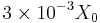
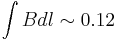
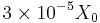
- Coherent-range γ-flux 107 Hz, total flux through the target 108 Hz
- Total accidental background rate is:
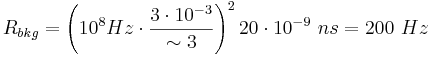
- Total pair production rate is:

- We have ~50% background if we leave the detector in the beam line.
- We can reduce it to 5% background at running at signal counting rate of 20Hz (such a rate assumes 100% acceptance).
- Total accidental background rate is:
- Converter
- Turning the dipole magnet on will get rid of the accidental background problem, but then the magnetic field effects will need to be dealt with. More work is needed for that with a real pair production simulation program, but judging from the Reference 2 above this might be doable even without a slit. (slit in this case would have to be less than 1 mm wide, which will interfere with the beam and will not allow us to sample the whole beam at one position of the slit).
- In Reference 2 they had ~10 times larger angle and ~5 times longer lever arm (factor of 50 in transverse distance at the detector). But it also have a ~6 times longer converter in terms of radiation length, and a factor of 8 lower photon beam energy (factor of ~20 in the multiple scattering angle). Therefore, if we use 50 times better resolution detector (~20μm pitch) we might be able to achieve similar results as in Reference 2 (relative measured asymmetry uncertainty of 3% mainly due to geometrical alignment uncertainties of ~1 mm ).