Difference between revisions of "Rearranging FCAL cables"
(Created page with "== Calorimeter Layout == <gallery> Image:fcal_2d.png | Fig. 1 FCAL layout Image:fcal2_2d.png | Fig. 2 FCAL 2 layout </gallery> * [https://halldweb.jlab.org/detectors/fcal2/c...") |
|||
| Line 38: | Line 38: | ||
Image:rocfcal4_adc.png | Fig. 3 rocfcal4 connect 4 lead glass channels to the new flash in Slot 19 | Image:rocfcal4_adc.png | Fig. 3 rocfcal4 connect 4 lead glass channels to the new flash in Slot 19 | ||
| + | </gallery> | ||
| + | |||
| + | <gallery> | ||
| + | Image:d2_2_mid_fcal2_recable.jpg | Fig. 1 D2-2-MID (FCAL 2) after rearranging signal cables | ||
| + | Image:d2_3_mid_fcal5_recable.jpg | Fig. 2 D2-3-MID (FCAL 5) after rearranging signal cables | ||
</gallery> | </gallery> | ||
Revision as of 16:18, 22 June 2023
Contents
Calorimeter Layout
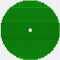
Fig. 1 FCAL layout
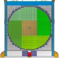
Fig. 2 FCAL 2 layout


VXS crate layout
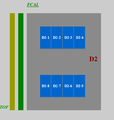
Fig. 1 Twelve FCAL VXS crates
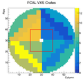
Fig. 2 Connection of FCAL signal cables to 12 VXS crates. Red box denotes the FCAL insert region.
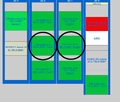
Fig. 3 Six FCAL crates on the north side. Circles denote crates connected to the FCAL2 insert region.
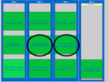
Fig. 4 Six FCAL crates on the south side. Circles denote crates connected to the FCAL2 insert region.


VXS crates connected to the FCAL2 insert region
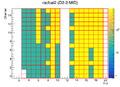
Fig. 1 ADC channel assignment (rocfcal2, north)
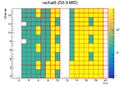
Fig. 2 ADC channel assignment (rocfcal5, north)
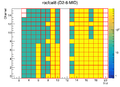
Fig. 3 ADC channel assignment (rocfcal8, south)
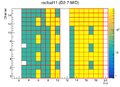
Fig. 4 ADC channel assignment (rocfcal11, south)


- Blue region corresponds to ADC channels connected to the FCAL2 insert region (21x21 lead glass modules). Yellow boxes correspond to channels connected to the region outside the insert.
- 108 ADC channels in each of four crates are connected to the insert region
- 238 ADC channels are used in each crate
Possible rearranging of cables
- Move 108 channels from the rocfcal2 (rocfcal8) crate connected to the insert to the rocfcal5 (rocfcal11) crate. The total number of channels in this crate: 108 + 108 = 216 (connect to 14 FADCs), see Fig. 1
- Move 126 channels in the rocfcal5 (rocfcal11) crate connected to the insert to the rocfcal2 (rocfcal8) crate. The total number of channels in this crate: 130 (remaining) + 126 = 256 (connect to 16 FADCs), see Fig. 2. Connect 4 remaining cables to other crates, see Fig. 3
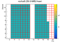
Fig. 1 rocfcal5 crate after re-cabling (216 channels, connected to all FCAL insert modules)
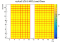
Fig. 2 rocfcal2 crate after re-cabling (256 channels, connected to all lead glass modules)
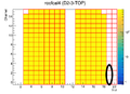
Fig. 3 rocfcal4 connect 4 lead glass channels to the new flash in Slot 19


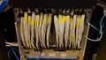
Fig. 1 D2-2-MID (FCAL 2) after rearranging signal cables
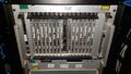
Fig. 2 D2-3-MID (FCAL 5) after rearranging signal cables

