Difference between revisions of "Testing of PMT dividers"
From GlueXWiki
| Line 30: | Line 30: | ||
Image:ccal_prot_cables1.jpg | Fig. 1 - Cables connected to the FCAL2 dividers (signal, HV, and LV) | Image:ccal_prot_cables1.jpg | Fig. 1 - Cables connected to the FCAL2 dividers (signal, HV, and LV) | ||
Image:ccal_prot_cables3.jpg | Fig. 2 - Cables connected to the FCAL2 dividers (signal, HV, and LV) | Image:ccal_prot_cables3.jpg | Fig. 2 - Cables connected to the FCAL2 dividers (signal, HV, and LV) | ||
| − | Image:ccal_prot_cables2.jpg | Fig. | + | Image:ccal_prot_cables2.jpg | Fig. 3 - Closer look of dividers |
| − | Image: | + | Image:ccal_prot_cables4.jpg | Fig. 4 - Patch panels: LV distribution for the 5x5 prototype (right) |
| − | + | Image:ccal_prot_cables5.jpg | Fig. 5 - Patch panel from the outside of the CCAL | |
| − | Image:ccal_prot_cables5.jpg | Fig. | + | |
</gallery> | </gallery> | ||
Revision as of 18:48, 13 February 2023
Bench tests
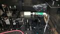
Fig. 1 Setup for testing PMT dividers
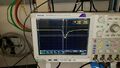
Fig. 2 Bypassed amplifier, small amplitude
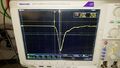
Fig. 3 Bypassed amplifier, large amplitude
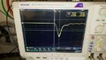
Fig. 3 Amplifier gain 3, small amplitude


Installing 5x5 prototype on CCAL
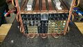
Fig. 1 - Front view of the CCAL
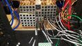
Fig. 2 - Rear view of the CCAL
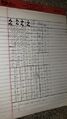
Fig. 3 - List of modules installe


Cables, and patch panels
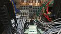
Fig. 1 - Cables connected to the FCAL2 dividers (signal, HV, and LV)
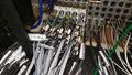
Fig. 2 - Cables connected to the FCAL2 dividers (signal, HV, and LV)
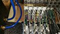
Fig. 3 - Closer look of dividers
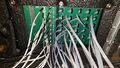
Fig. 4 - Patch panels: LV distribution for the 5x5 prototype (right)
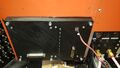
Fig. 5 - Patch panel from the outside of the CCAL


