University of Connecticut Active Collimator Station Tutorial
On January 7th, 2014, the active collimator station (computer name actcol-station) was positioned in room F117 of the CEBAF building at Jefferson Lab. This wiki page serves to teach how the station operates.
Configuration of the Station
Figures 1 and 2 serve to show the user how the active collimator station is connected to the actcol-station PC. I have labeled various components in Figure 1; their descriptions are below. Figure 2 shows the user how to connect everything to the PC.
(1 and 2) Collimator and amplifiers Collimator and The signals from the tungsten plates within the active collimator are picked up and transmitted to the amplifiers via an SMA to BNC cable.
3: On the "downstream" end of the amplifiers, there is a connection for a BNC to BNC cable that transmits the amplified signals to the "BNC box" (5). There is also a DB9 to Ethernet adapter; connecting an Ethernet cable from the Ethernet splitter (4) supplies power and information from the terminal board (6).
4: An Ethernet splitter for power distribution and communication with the terminal board (6). From right to left: power source from F100-PS power supply (not pictured), four power sources for the amplifiers, connection for terminal board.
5: A BNC to BNC cable connects each amplifier to the "BNC box." The BNC box is then connected to the terminal board (6) and PC via a ribbon cable. Connect the "BNC box" end of the ribbon cable to the "P3" input in the back of the BNC box.
6: The terminal board. Connect the "terminal board" end of the ribbon cable to this. See Figure 2 for a better view.
Connect the remaining end of the ribbon cable to the data acquisition card in the PC. The gain setting for the amplifiers is also chosen within the LabVIEW program, which is discussed next.
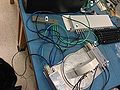
Figure 1
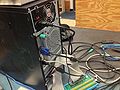
Figure 2


Feel free to contact me at john DOT bartolotta AT uconn DOT edu with any questions.