Start Counter Commissioning
From Hall D Ops Wiki
Contents
Displaying the Start Counter EPICS GUI
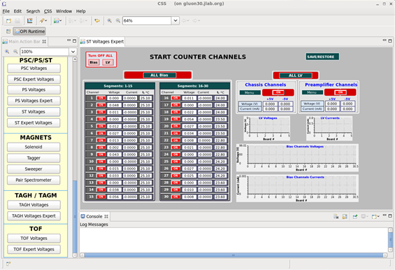
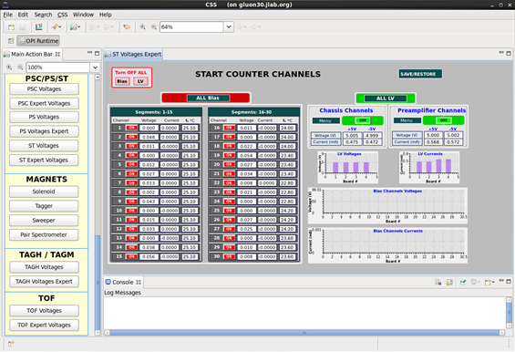
- To operate the Start Counter (ST) for the commissioning run you must begin by selecting the ST Expert Voltages button located in the main action bar to the left in the CSS workspace.
- The ST will be powered off and the expert voltages GUI will look something like the following:
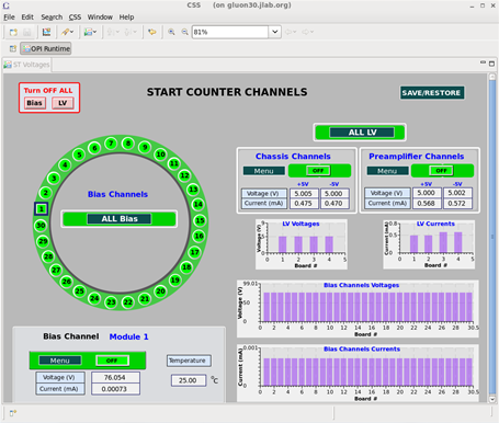
- The ST Expert Voltages GUI is more useful than the voltages GUI. The expert GUI allows the user to view all of the thermocouple readings of each individual ST channel. Furthermore, it allows the user to view the bias being supplied to each of the channels as well as the current that is being drawn for each channel.
- This page should remain up when progressively ramping up the bias to the nominal operating voltage since it is this page that provides more detailed information which needs to be monitored during the commissioning process.
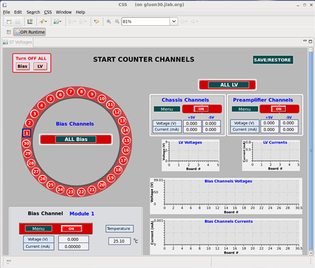
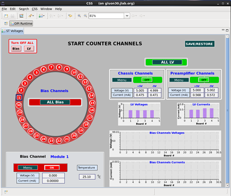
- The alternative ST Voltages display will look like the following:
- The ST Voltages GUI is useful in the sense that the user may view the orientations of the ST channels as they are oriented on the actual detector. This view is looking downstream, i.e. the beam is hitting you in the back of the head.
Displaying the ST Scalers GUI
- During the commissioning process of the ST it is imperative that the ST Scalers GUI be displayed on one of the screens in the control room.
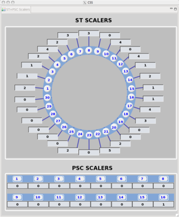
- The ST Scalers GUI, like the others mentioned above, can be activated by left clicking the ST/PS Scalers button located in the main action bar to the left in the CSS workspace. It will look like the following:
- This GUI will display the scaler rate in units of Hz and should be monitored closely when slowly ramping up the ST bias which will be discussed below.
Slowly Ramping the ST Bias
- Unique to the commissioning of the ST, the ST experts have decided that the bias supplied will be done in an predetermined incremental manner.
- During the incremental ramp up of the bias, close attention must be paid to all available ST EPICS GUIs so that any potential damage to the detector is kept to an absolute minimum.
- In order to carefully ramp up the ST bias, the operator must begin by restoring the preset bias parameters to the lowest available setting.
- This is done by left clicking the SAVE/RESTORE button in the top right corner of the CSS workspace.
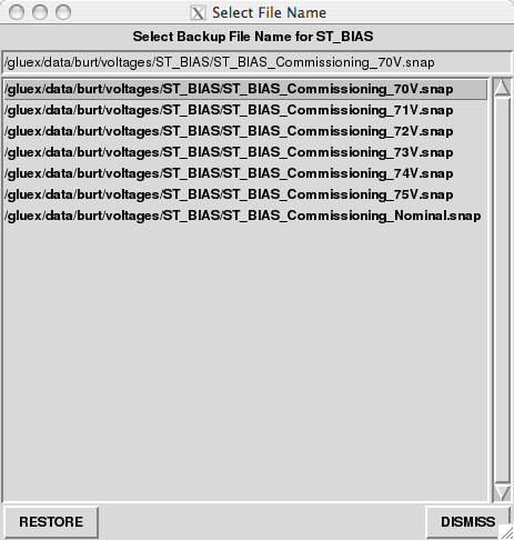
- Next, the operator should select the ST: Restore BIAS parameter setpoints option located at the bottom of the drop down menu. The following window will appear:
- Here you will notice that there are 7 possible configurations of bias parameters. The portion of the file name after ST_BIAS_Commissioning_ indicates the approximate amount of bias that will be applied to each of the SiPMs when that particular "snap" is loaded.
- Here the lowest setting is approximately 70 V for each detector and the Nominal setting contains the parameters to operate the ST at full power.
- The operator should begin by selecting the lowest possible configuration of 70 V prior to supplying any power to the detector.
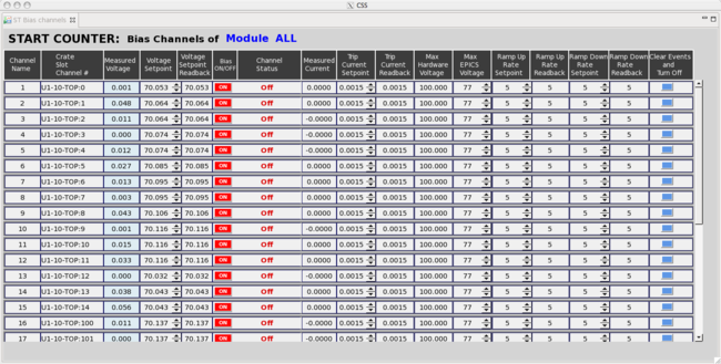
- In order to ensure that the appropriate bias setting have been restored, left click the ALL Bias button in the ST Expert Voltages GUI and select the third from the top option labeled Show ALL Bias Channels. The resulting window that will be displayed will be the following:
- While operating inside this window the operator will is be able to adjust the ST LV and Bias parameters. However, these values have been specifically configured so it is imperative that YOU DO NOT MODIFY ANY PARAMETERS without consulting a Start Counter expert first!!!
- The column labeled Voltage Setpoint indicates the amount of bias that will be appilled the ST upon ramping up the power. It is is imperative here that the Voltage Setpoint here indicate the amount of bias that was indicated by the snap file that was loaded prior to applying bias to the ST.
- Once the voltage set point has been confirmed to the value set by the snap file the operator can proceed to the next step.
Utilizing the ST Bias Distribution GUI's During Commissioning
- From either ST voltages GUI you will be able to control the LV and Bias power distributions to the Start Counter.
- In order to properly supply LV and Bias to the Start Counter you must follow these steps IN THIS EXACT ORDER:
- Turn on the LV power system (pre-amplifier channels & chassis channels). Once the LV monitoring displays are green the operator may proceed.
- The expert display will look like the following when the LV has been turned on:
- The control display will look like the following when the LV has been turned on:
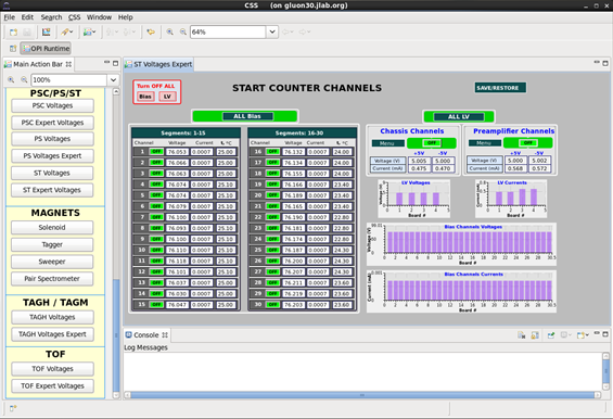
- Once the LV power has been ramped up you may turn on the Bias power system. Once all the channel monitoring buttons are displayed green the Start Counter is fully powered and now fully operational.
- The expert voltages GUI will resemble the following:
- The voltages GUI will resemble the following:
- Once the ST is fully powered to the 70 V setting, the operator should observe the current monitors, thermocouple readouts, and the scaler values.
- At the lowest possible setting you will most likely not see any activity in the ST since this bias is well below the breakdown voltage of the SiPMs.
- Nominal behavior of the ST is the following:
- Temperature should be between approximately 22 - 30 deg Celsius
- Current should be drawing around 700
 A (read on screen as 0.0007)
 - Bias should be reading approximately same values as the set points observed in the Show ALL Bias Channels window.
- If behavior is observed to be normal then the operator may proceed with the next ramping stage.
Ramping the ST to Full Operating Power
- To ramp the bias to the next stage, left click the SAVE/RESTORE button in the top right corner of the CSS workspace as was done previously.
- Select the next snap file with the indicated bias setting that is 1 V above the current setting. For commissioning purposes the next bias setting is 71 V.
- Once you restore this setting the bias will IMMEDIATELY BEGIN TO RAMP UP!!! Thus, it is crucial that you select the correct snap file.
- As before, once the bias has stabilized carefully observe the ST parameters as well as the ST scalers GUI.
- Again, the operator will most likely not see any activity until they have reached the bias setting of 74 V.
- Continue this process until the nominal operating voltage has been reached.
- As a reminder, a rate above 250 kHz would indicate that the discriminator thresholds are to low, or there potentially exists a more serious problem.
- If there is any odd behavior observed while ramping up the ST, turn the ST bias and low voltage off and contact an ST expert.
Powering off the ST
- To turn off the Start Counter you must follow these steps IN THIS EXACT ORDER:
- First, ramp down the bias power system. Once all the channel monitoring buttons are displayed red and no bias is being supplied to the ST1s you may proceed. The GUI should resemble that of the sixth and seventh images in this wiki.
- Second, ramp down the LV power systems. One the LV monitoring buttons are displayed red the Start Counter is powered off. The GUI should now resemble that of the first and second images presented in this wiki.
