Difference between revisions of "Forward Drift Chamber Shift"
(→Expert personnel) |
(→The Forward Drift Chambers) |
||
| Line 17: | Line 17: | ||
due to the LV applied on the detector pre-amplifieres. | due to the LV applied on the detector pre-amplifieres. | ||
A cooling system using Fluorinert is used to keep the temperature on the | A cooling system using Fluorinert is used to keep the temperature on the | ||
| − | pre-amplifiers within the permissible limits. <font color=red> The LV system should never be turned ON if the cooling system doesn't work </font>. | + | pre-amplifiers within the permissible limits. <font color=red> The LV system should never be turned ON if the cooling system doesn't work </font>. Note, however, that |
| + | the interlock should safeguard against this condition. | ||
== Routine operation== | == Routine operation== | ||
Revision as of 16:36, 3 July 2014
The Forward Drift Chambers
The Forward Drift Chamber (FDC) system consists of four identical packages (named FDC1 to FDC4), each having six chambers or cells (named CELL1 to CELL6). These are planar drift chambers with both anode wires and cathode strips being readout, in total 12,672 channels.
The cells within a package have independent gas volumes, but are separated with a flexible mylar membrane. Therefore, the pressure difference between neighboring cells should never exceed 30 Pa and should normally be less than 5 Pa.
Positive (up to 2200 V) and negative (up to 500 V) HV is applied on the sense and field wires respectively with currents not exceeding 3 microA per HV channel .
The detector (including cables) emits a total power of about 1500 Watt, of which about 900 Watt inside the magnet, due to the LV applied on the detector pre-amplifieres. A cooling system using Fluorinert is used to keep the temperature on the pre-amplifiers within the permissible limits. The LV system should never be turned ON if the cooling system doesn't work . Note, however, that the interlock should safeguard against this condition.
Routine operation
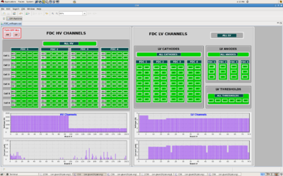
The most important task for the shift workers is to monitor the parameters (using GUIs) and report any changes from the normal operation for the following FDC related subsystems: High Voltage, Low Voltage (including thresholds), Gas system, and the Cooling system. A description of how to bring up the corresponding GUI screens and how to operate them can be found in Section Slow Controls. The HV and LV subsystems, as well as the Gas and Cooling systems have common GUIs. The GUIs are designed to show green color if all the parameters in a certain subsystem/subgroup are within the limits. If any of the parameters is out of limits the background for the corresponding subsystem/subgroup will turn red. Examples of the GUIs are shown in Figs. 1 and 2.
The shift workers are allowed, using the GUI, to turn ON and OFF all the HV and LV (including thresholds) systems, as well as parts of them or the individual channels. Instructions how to do this are given in Section Slow Controls, but the general rule is either to bring the pop-up menu with left click on the group title (like "ALL HV", or "FDC 1") or to click on the individual channel knob (the knob title shows the action to be taken after pressing it). For example, in case a HV channel trips, one should press the corresponding channel knob once (acknowledging the trip) and then again to turn it on. The corresponding voltage parameters, like rump up/down rates, trip currents, set voltage values etc. cannot be changed by the shift workers. The Gas and cooling system GUI is only to be monitored by the shift workers; the parameters there cannot be changed.
In addition to the operations using GUIs, the shift workers should visually check the gas panel in the Hall using the camera "halldaxis7" with remote control installed there, and make sure all the bubblers operate normally. For instructions how to operate the camera, refer to Section Slow Controls. Once per shift the workers are supposed to record the manometer values and inspect other components in the gas room; see Section Gas System.
Operations beyond what is specified above shall only be performed by the system expert or under his/her direction.
Interlocks
To prevent damage of the equipment in situations explained in the first paragraph (where the corresponding critical parameter limits were highlighted with red) interlock systems are implemented. Hardware interlock is used to turn OFF the power of the LV crate in case the cooling system fails. Software (PLC based) interlock system is implemented to turn off the gas supply if the pressure between any two neighboring cells exceeds 30 Pa. The HV and LV modules are set to immediately turn off the voltage if the current exceeds the corresponding limit. Setting the voltage channel back should be done only manually by the operator. We DO NOT use the automatic feature to keep the voltage (for a certain time) such that the current is at the limit.
Expert personnel
The individuals responsible for the operation of the FDC are shown in the following table. Problems with normal operation of the FDC should be referred to those individuals and any changes to their settings must be approved by them. Additional experts may be trained by the system owner and their name and date added to this table.
| Name | Extension | Date of qualification |
|---|---|---|
| Lubomir Pentchev | 269-5470 | June 3, 2014 |

