Difference between revisions of "Gas System Shift"
(→Gas System Experts) |
|||
| (3 intermediate revisions by one other user not shown) | |||
| Line 13: | Line 13: | ||
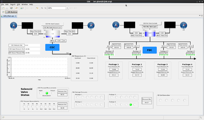
[[Image:gassystem_mainGUI.png | thumb | 400px | Fig. 6. Main GUI to monitor and control the gas system. ]] | [[Image:gassystem_mainGUI.png | thumb | 400px | Fig. 6. Main GUI to monitor and control the gas system. ]] | ||
| − | + | Figure 1 shows the gas system for both the FDC and CDC chambers. A more readable version can be found here [[File:gassystemP&I.pdf]] | |
The gas system provides the operating gas mixtures for the two tracking detectors FDC and CDC. The two detectors have two independent mixing stations to provide the appropriate gas mixture for the detectors. In case of the FDC this is a 40%/60% Argon/CO2 gas mixture while for the CDC it is a 50%/50% Argon/CO2 mixture. The gas is provided by high pressure (2500psi Argon, 800psi CO2) gas bottles located outside the gas shed (room 401 building 202). The gas pressure is regulated down to 50psi and directed into the gas shed. The gas mixing is done using BROOKS mass flow controllers for each gas type. The gas is filled into a blending tank from which the gas is enriched with propyl alcohol before it is sent to the upper platform in the hall. The pressure in the blending tank is controlled by the PLC system and kept between 7 and 12 psi. From the blending tank the gas is going through the alcohol bubbler system that is located inside a refrigerator. | The gas system provides the operating gas mixtures for the two tracking detectors FDC and CDC. The two detectors have two independent mixing stations to provide the appropriate gas mixture for the detectors. In case of the FDC this is a 40%/60% Argon/CO2 gas mixture while for the CDC it is a 50%/50% Argon/CO2 mixture. The gas is provided by high pressure (2500psi Argon, 800psi CO2) gas bottles located outside the gas shed (room 401 building 202). The gas pressure is regulated down to 50psi and directed into the gas shed. The gas mixing is done using BROOKS mass flow controllers for each gas type. The gas is filled into a blending tank from which the gas is enriched with propyl alcohol before it is sent to the upper platform in the hall. The pressure in the blending tank is controlled by the PLC system and kept between 7 and 12 psi. From the blending tank the gas is going through the alcohol bubbler system that is located inside a refrigerator. | ||
| Line 24: | Line 24: | ||
== Shift Check list == | == Shift Check list == | ||
The following operation parameters of the gas system needs to be checked once per shift: | The following operation parameters of the gas system needs to be checked once per shift: | ||
| − | # In the gas shed | + | # In the gas shed (use camera "[http://halldaxis1.jlab.org halldaxis1]") |
#* Are the mass flow controller boxes properly operating? (display as in figure 2 showing channel 1 to 4) | #* Are the mass flow controller boxes properly operating? (display as in figure 2 showing channel 1 to 4) | ||
#* Is blending engaged? (blinking "M" and "S") (see figure 2) | #* Is blending engaged? (blinking "M" and "S") (see figure 2) | ||
| Line 55: | Line 55: | ||
| Lubomir Pentchev || align=center | 269-5470 || align=center | June 4, 2014 | | Lubomir Pentchev || align=center | 269-5470 || align=center | June 4, 2014 | ||
|- | |- | ||
| − | | Scot Spiegel || align=center | | + | | Scot Spiegel || align=center | 269-5900 || align=center | June 4, 2014 |
|} | |} | ||
Latest revision as of 14:56, 1 December 2017
Contents
Gas System for tracking chambers
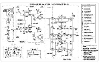
Figure 1 shows the gas system for both the FDC and CDC chambers. A more readable version can be found here File:GassystemP&I.pdf The gas system provides the operating gas mixtures for the two tracking detectors FDC and CDC. The two detectors have two independent mixing stations to provide the appropriate gas mixture for the detectors. In case of the FDC this is a 40%/60% Argon/CO2 gas mixture while for the CDC it is a 50%/50% Argon/CO2 mixture. The gas is provided by high pressure (2500psi Argon, 800psi CO2) gas bottles located outside the gas shed (room 401 building 202). The gas pressure is regulated down to 50psi and directed into the gas shed. The gas mixing is done using BROOKS mass flow controllers for each gas type. The gas is filled into a blending tank from which the gas is enriched with propyl alcohol before it is sent to the upper platform in the hall. The pressure in the blending tank is controlled by the PLC system and kept between 7 and 12 psi. From the blending tank the gas is going through the alcohol bubbler system that is located inside a refrigerator.
The alcohol bubbler in the glass tube should always bubbling and the level of alcohol should be between the two indicator lines labeled FULL and ADD (see figure 3) drawn on the glass. The level of alcohol in the glass bubbler should be recorded once per shift and the expert on call should be notified if refilling is required.
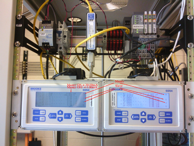
The gas blending (mixing of Argon and CO2) is in operation if the letters "M" and "S" on the display (see figure 2) of the two mass flow controller boxes are blinking. Channel 1 is the master and is set by a PLC current source based on the pressure in the mixing tank. The values are either 4mA (mass flow is off) or 20mA (mass flow is on). The slaves provide the mass flow according to the maximum number setting (PV max and SP max) of the master times the blending percentage of the slave.
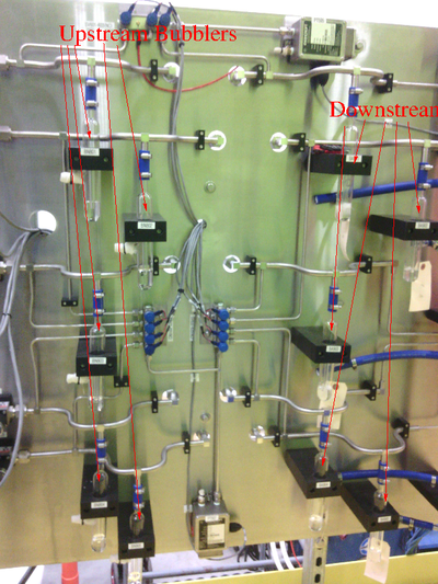
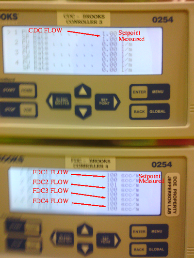
The gas is distributed to the FDC and CDC through mass flow controllers located on the gas panel on the upper platform in the hall. Mineral oil bubblers (see figure 4) on the upstream end of the detector (should never bubble) protect the detector from over pressure while the bubblers at the detector exhaust (should always bubble) protect the chambers from back flow. The controller boxes (see figure 5) show the mass flow settings for the CDC and FDC.
Shift Check list
The following operation parameters of the gas system needs to be checked once per shift:
- In the gas shed (use camera "halldaxis1")
- Are the mass flow controller boxes properly operating? (display as in figure 2 showing channel 1 to 4)
- Is blending engaged? (blinking "M" and "S") (see figure 2)
- Is the alcohol level between the two white lines in the glass tube? (see figure 3)
- Is the refrigerator running? (40 degree F)(see figure 3)
- On the platform in the hall (use camera "halldaxis7"; for instructions refer to Section Slow Controls )
- Are all the upstream bubblers calm (NO bubbles)? (see figure 4)
- Are all the downstream bubblers active (bubbles)? (see figure 4)
- Are all the mass flow set-points and read-backs equal and the values meet the operation parameters? (see figure 5)
If any of the readings are outside the expected range, call the gas expert.
Monitoring and Controls
The Main GUI of the gas system is shown in figure 6. From this GUI the operation parameters of the gas system can be monitored and potentially changed. Any change has to be approved by the gas system and detector experts (FDC/CDC). The gas pressure of the system is measured and monitored at various locations within the gas system and the detectors and displayed on the GUI.
Gas System Experts
The individuals responsible for checking that the gas system is ready to take data and setting its operating parameters are shown in following table. Problems with normal operation of the gas system should be referred to those individuals and any changes to their settings must be approved by them. Additional experts may be trained by the system owner and their name and date added to this table.
| Name | Extension | Date of qualification |
|---|---|---|
| Benedikt Zihlmann | 269-5310 | June 4, 2014 |
| Lubomir Pentchev | 269-5470 | June 4, 2014 |
| Scot Spiegel | 269-5900 | June 4, 2014 |
