Difference between revisions of "DIRC Shift"
(→DIRC LED System Stop functioning) |
(→Expert personnel) |
||
| Line 76: | Line 76: | ||
|- | |- | ||
| Justin Stevens || align=center | 269-7237 || align=center | 1/25/19 | | Justin Stevens || align=center | 269-7237 || align=center | 1/25/19 | ||
| − | |||
| − | |||
|} | |} | ||
Revision as of 12:41, 5 January 2023
Contents
The DIRC
The DIRC is a plane of 4 independent boxes each containing 12 fused silica radiator bars with a size of 4.9 m x 35 mm x 17.25 mm, which are housed in an honeycomb shell with a thin aluminum skin. Each pair of bar boxes is optically coupled to a water-filled expansion volume, known as the Optical Box (OB). The Cherenkov photons from the radiators propagate through the water-filled OB and are detected by an array of Hamamatsu H12700 multi-anode photomultiplier tubes in each OB.
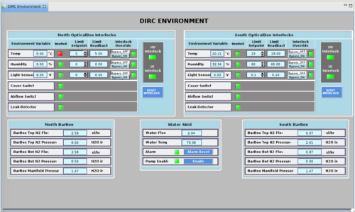
Checking the environment
The important elements of the DIRC environment are the nitrogen purge of the bar boxes which are monitored by flow and pressure sensors in the GUI above. In addition, the optical box environment is monitored by a temperature and light sensor to ensure the environment in the dark box is appropriate for the electronics and PMTs. Finally a water leak sensor is located beneath the optical box which will disable the low and high voltage in the case of a water leak.
The H12700 multi-anode PMTs are operated inside a dark box attached to the optical box, which allows for maintenance of the system while the bases are powered off. An interlock on the low and high voltage to the electronics and PMTs protects the readout system from damage. A proximity sensor provides an interlock to shut off the LV and HV if the dark box is opened, exposing the PMTs to external light. A fan provides cooling to the electronics to prevent excessive temperatures inside the dark box, and an interlock will shut off the LV and HV if the fans are not operating or the temperature exceeds the safe value.
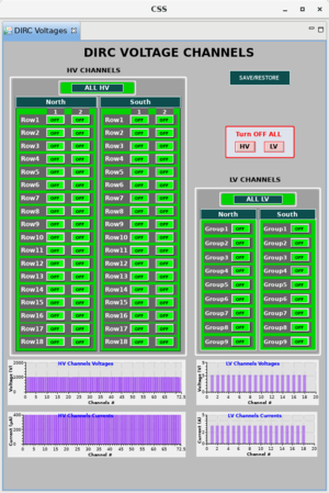
Voltage controls
Each DIRC electronics module (instrumenting three MAPMTs) is powered by the Wiener LV modules at 5V, separated into 9 groups for each optical box (North and South). To turn on the LV supplies for each modules push the "ON" button and verify the voltage read back matches the figure given here. The high voltage can be set individually for each DIRC electronics module as seen in the HV GUI. To turn on the HV supplies click the "South" box and select "Turn ON all HV South channels"
LED Pulser controls
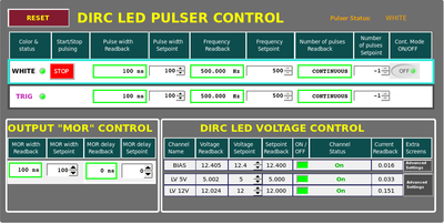
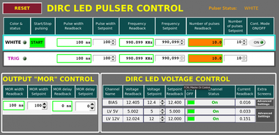
The DIRC PMTs are monitored by an LED pulser which injects pulsed low intensity light inside the optical box. The GUI above shows the LED pulser GUI which can be controlled to set the pulser rate and LED bias magnitude. These parameters should not be changed unless you're directed to do so by an expert.
Frequent Reoccurring Problem and Quick Solution
DIRC Communication Error at run start
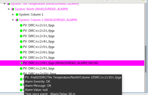
- Description on the Symptoms: When starting a new run, one of the DIRC FPGA boards may lose communication resulting in a Magenta communication error in the Alarm Tree. On the rcGUI, an error should also appear, prevent you from starting the run.
- Solution
- Stop the run if it's not already.
- On the rcGUI follow the sequence (Reset->Configure->Download->Prestart->Start). This should re-configure the FPGA boards and a new run should begin normally.
- Make a e-log entry.
- Call DIRC expert if problem was not resolved.
DIRC Low Voltage Refuse to turn on
- Description on the Symptoms: Often DIRC LV group 9 will trip due to current over the limit. It will refuse to ramp and run at preset value of 5.2 V.
- Solution
- Check the preset value to 5.0 V and ramp first.
- Let group 9 run to stabilize for few minutes.
- Then ramp to 5.2 V.
DIRC LED System Stop functioning
- Description on the Symptoms: during the data taking (specially the first run after a planned or opportunistic maintenance work), the root_spy monitoring will not display any DIRC LED data. If one opens the DIRC_LED control control, one would see the LED frequency showing a crazy value like the one above. (example plot showing the LED frequency set point and read back as 990k Hz).
- Cause: since the pulsing system (crate) is shared between FCal, CompCal and DIRC. Rebooting the Pulser crate will cause DIRC pulser frequency set point to go to the a crazy value.
- Solution: Set frequency setpoint back to 500 Hz, make sure the pulse width is 100 ns, enable the Cont. Mode ON/OF (turning it on, it should be flashing). Then click start bottom. The system should be restored.
Expert personnel
The individuals responsible for checking that the DIRC is ready to take data and setting its operating parameters are shown in following table. Problems with normal operation of the DIRC should be referred to those individuals and any changes to their settings must be approved by them. Additional experts may be trained by the system owner and their name and date added to this table.
| Name | Extension | Date of qualification |
|---|---|---|
| Justin Stevens | 269-7237 | 1/25/19 |
