Difference between revisions of "Procedure installing solid target"
From Hall D Ops Wiki
(→Procedure:) |
(→Procedure:) |
||
| Line 8: | Line 8: | ||
# Remove the beam profiler if necessary. | # Remove the beam profiler if necessary. | ||
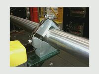
# Open the two hose clamps holding the beam tube to the fixed V-blocks, see 1st picture. [[File:mms_picture.jpg|200px|thumb|left|hose clamp]] | # Open the two hose clamps holding the beam tube to the fixed V-blocks, see 1st picture. [[File:mms_picture.jpg|200px|thumb|left|hose clamp]] | ||
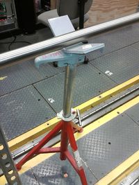
| − | # Spin the jack adjustment nut on the adjustable V-block rest until the beam line is high enough to allow the target mount tube to be easily removed. See the jack on the 2nd picture [[File:beam_line_jack.jpg|200px|thumb|left|Beam Line jack]] | + | # Spin the jack adjustment nut on the adjustable V-block rest until the beam line is high enough to allow the target mount tube to be easily removed. See the jack on the 2nd picture. [[File:beam_line_jack.jpg|200px|thumb|left|Beam Line jack]] |
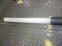
# Remove the target mount tube. <span style="color:red">Make sure you support it horizontally to not break the thin white extremity of the tube (fragile) </span>, see 3rd photo showing the white extremity: [[File:solid_target_end.jpg|200px|thumb|left|White tube extremity (fragile)]] | # Remove the target mount tube. <span style="color:red">Make sure you support it horizontally to not break the thin white extremity of the tube (fragile) </span>, see 3rd photo showing the white extremity: [[File:solid_target_end.jpg|200px|thumb|left|White tube extremity (fragile)]] | ||
# Remove the current target and replace it with the desired one. The targets are stored in a yellow plastic bin attached to one of the beam line post. | # Remove the current target and replace it with the desired one. The targets are stored in a yellow plastic bin attached to one of the beam line post. | ||
# Insert the target mount tube. Make sure you support it horizontally to not break the thin white extremity of the tube (fragile). Slide it up to the nominal target Z-position marked by a white ring painted on the target tube. | # Insert the target mount tube. Make sure you support it horizontally to not break the thin white extremity of the tube (fragile). Slide it up to the nominal target Z-position marked by a white ring painted on the target tube. | ||
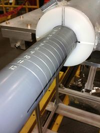
| − | If the orientation of the target matters (e.g. we are using the Cross target or the Triangle target), align the black line on the target tube to the black line on the support tube. See 4th picture. [[File:solid_target_alignment.jpg|200px|thumb|left| | + | If the orientation of the target matters (e.g. we are using the Cross target or the Triangle target), align the black line on the target tube to the black line on the support tube. See 4th picture. [[File:solid_target_alignment.jpg|200px|thumb|left|Orientation marks]] |
| − | + | # Lower the beam line down onto the two fixed V-blocks by spinning the adjustment nut on the adjustable V-block rest. Spin the nut a couple of times further to ensure the temporary V-block is not in contact with the beam line. | |
| − | + | # If necessary, Reinstall the profiler. | |
| − | + | # Update database to reflect the target change: procedure to update the target status in the database. To do this, go here | |
Revision as of 11:20, 13 October 2014
Procedure to install/change solid targets
Experts: Matt Marchlik, Alexandre Deur, Tim Withlatch
Procedure:
- If needed, request Radiological survey of the target area.
- Remove the beam profiler if necessary.
- Open the two hose clamps holding the beam tube to the fixed V-blocks, see 1st picture.
- Spin the jack adjustment nut on the adjustable V-block rest until the beam line is high enough to allow the target mount tube to be easily removed. See the jack on the 2nd picture.
- Remove the target mount tube. Make sure you support it horizontally to not break the thin white extremity of the tube (fragile) , see 3rd photo showing the white extremity:
- Remove the current target and replace it with the desired one. The targets are stored in a yellow plastic bin attached to one of the beam line post.
- Insert the target mount tube. Make sure you support it horizontally to not break the thin white extremity of the tube (fragile). Slide it up to the nominal target Z-position marked by a white ring painted on the target tube.
- Lower the beam line down onto the two fixed V-blocks by spinning the adjustment nut on the adjustable V-block rest. Spin the nut a couple of times further to ensure the temporary V-block is not in contact with the beam line.
- If necessary, Reinstall the profiler.
- Update database to reflect the target change: procedure to update the target status in the database. To do this, go here


