CAEN V792N ADC
This short section describes the behavior of the V792N ADC from CAEN. In the current setup a blue LED is coupled to an XP2020 PMT by an optical fiber and the light intensity is adjusted such that the PMT provides a signal between about 10mV and 40mV. The HV of the PMT is set at -1700V. The signal is connected to an amplifier of 10 and then connected to a linear FAN IN/OUT. The DC output of the FAN can be adjusted and is changed between 0 and 15mV
in this test. The ADC V792N is a charge integrating ADC with a 12bit digitizer and has a sensitivity of 100fC per channel with a maximum at 400pC. There is a built in threshold for each channel that varies between about 50 and 60 bins. In this test channel 4 of the ADC is used and its threshold is found to be about 55 as shown in the next plot. This corresponds to a threshold of 5.5pC. The gate length is set at 63.6ns.


Note that the red histogram is the result when the signals from the PMT were present but the total integrated charge is below 55*50fC and hence below the threshold of the ADC channel. The pink curve is a fit to the black histogram that is the pedestal generated by a random trigger not correlated to the LED trigger. The pictures on the left show scope shots of signals from the XP2020 PMT response on the blue LED. The DC offset here is set to about -4.4mV. In the first picture the base line of the signal is slightly below the -4.4mV line because there is an additional low frequency noise of about 0.5mV peak to peak that will determine the width of the pedestal once the total integrated charge of the pedestal is above the internal threshold of 5.5pC.
In the following the DC offset is increased in steps to find the level where the total integrated charge from the LED trigger event is above threshold. The following plots show the ADC spectrum of the same channel at DC offsets of -3.5mV, -3.9mV, -4.0mV, -4.2mV, -5.0mV and -9.6mV:


One can see that at a -3.9mV DC offset the signal starts to appear meaning that the integrated value is above the built in threshold. At -4.0mV DC offset the ADC signal is clearly discernible the separated from the pedestal. The smaller peak in red around channel 54 represent those events where the total integrated charge is below the built in threshold. At a DC offset of -4.2mV almost all events are above the threshold. From this point on any additional
DC offset will move the whole ADC spectrum to higher values. The width of the pedestal should not change and also the distance between the pedestal and the signal peak should not change due to such a shift. This behavior is clearly seen in the last two plots where the DC offset has been set to -5.0mV and -9.6mV respectively.
Lets assume we have a signal of -10mV amplitude triangular shape with a duration of 30ns. The 50 termination results in an integrated charge of
 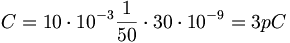 . Because the internal threshold in the above example of channel 4 is 5.5pC such a signal will end up in bin 55. In order to make sure that this signal gets above the internal threshold of 5.5mV it is necessary to add 2.5pC to the signal charge. This can be achieved by a DC offset. In the above example the integration time is 63.6ns. This results in a necessary minimum DC offset of
 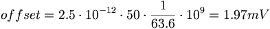 . Therefor a minimum about -2mV DC offset is necessary for a 10mV signal to be above the ADC internal threshold. In the above example a DC offset of -3.9mV was necessary to start seeing signals above pedestal. This means that there is a small miss-match between the ADC reference zero and the oscilloscope reference zero of about 2mV.
According to the manual of the charge integrating ADC 1881M from LeCroy the internal pedestal (threshold) for a channel is between 200 and 800 counts. The full range of the ADC is 13 bits corresponding to 8192 counts. The resolution of the ADC is 50fC per channel. This means that the internal threshold is between 10pC and 40pC. Following the above example and assuming a 10pC internal threshold would require a minimum DC offset of about -5.52mV.