CDC 12 12 2007
News on tracking
Although I can not show plots yet some progress was made concerning the tracking. Remember that hitpoints in the CDC are actually hit circles (cylinders).
Cosmic track finding: this code was already written weeks ago. How does it work (summary):
- ) All 2-combinations of hit-circles are looped over
- ) 4 tangents are calculated
- ) other members of the 4 possible tracks are searched for (within the error on the hit-circles)
- ) a track is a possible track if it contains at least 3 hits
- ) the track which has its members closest to the one of the tangents is selected
- ) only one track/event is selected
Track fitting: this code is recently added, how does it work:
- )
 are the coordinates of the center of the hit-circle and the hit-radius respectively
 - )
 is the straight line that is fit (2D fitting, we have no z-information)
 - )
 minimization by MINUIT is used
 - ) Following function is minimized:
![\sum _{{i=1}}^{{N}}\left[{\frac {r_{i}^{2}-{\frac {\left(Ax_{i}+By_{i}+1\right)^{2}}{A^{2}+B^{2}}}}{E_{{r_{i}^{2}}}}}\right]^{2}](/wiki/images/math/c/1/e/c1ef5b3220029bc3a3ee54080018b766.png) ,
,  is the number of hits,
  is the error on
  , for the moment, all errors are set equal to each other. The minimization demands that the distance between the fit line and the center of the hit has to be equal or as close as possible to the hit-radius.
- ) Residuals are calculated
I hope to produce plots showing residuals soon.
Interposer, preAmp, and signal cable
The new preAmp, the interposer, and the signal cable arrived at CMU (12/6/2007). The first test that was performed was to apply 3.2 V on the preAmp board without anything connected to it: the board drew a current of 280 mA, this is ecact the current that is specified, good! After connecting the signal cable to it the current that was drawn doubled, not so good. It turned out the the piece of signal cable sticking out of the connector was touching the heat sink and making shorts. After cutting off this piece of cable the preAmp was again drawing 280 mA.
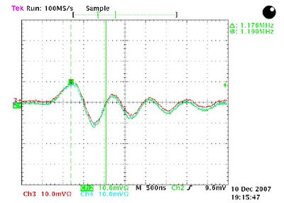
Channel 1 and 2 of the signal cable were connected to our postAmp and all the other channels were left open. When the preAmp is NOT connected to the HV distribution board a noise(?) signal can be observed on the scope (shown in figure 1).
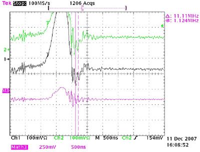
When connected to the HV-distribution board the output signals looked like an 10 MHz oscillation. The signal seen on the oscilloscope is shown in figure 2.
This does not look a like CDC signal. Another short was expected.
After inspecting the preAmp visually a short was found on the output connector: it was soldering sitting between to pins. This soldering was easy to remove. However, it did not improve/change the situation. After this the signal cable was checked for shorts - no shorts were detected. Then the signal cable was connected to the preAmp and the resistance was measured between OUTA and OUTB:
- ) 16 channels have a resistance of 950 Ohm -> these are the populated channels (#1-8 and #17-24)
- ) 7 channels were open -> these are the not populated channels (#10-16)
- ) 1 channel was shorted -> #9
At this point Fernando was contacted: he said that the channel #9 should not be shorted but that this should not influence the proper working of the preAmp. Next test was to terminate all populated channels that are not read out with 100 Ohm. This was done with no result (2 channels were connected to the postAmp, all the other channels except the not populated ones were terminated with 100 Ohm including the signal IN channel was terminated, the not populated channels were left open). After this I soldered all populated channels to the connector that goes to the postAmp and left the signalIN channel terminated, again: no change, the same oscillation as shown in figure 2 is observed.
Last test that was performed was to terminate ALL populated channels and to connect nothing to the postAmp (suggested by Fernando). The differential signal of channel #1 was read out by the scope. The signal can be seen in figure 3, it is difficult to interpret a differential signal but I do not see improvement.
In order to compare with the situation before I added to scope plots made with the old CLAS preAmp (it is a different preAmp as the new one - so it is not completely fair to compare). In figure 4, the signal coming from the CLAS preAmp can be seen when there was no HV applied on the CDC, in figure 5 a signal can be seen. Figure 4 can be compared with figure 2. I tried to see if I could distinguish a CDC signal on the scope, using the new preAmp and our postAmp. No signal could be distinguished, the same as in figure 2 was observed.
From this point on I always measure right after the signal cable (no postAmp, all populated channels terminated with 100 Ohm). Next test (suggested by Fernando) was to disconnect the the HV supply cable from the HV distribution board. I did this in two steps, first only the HV supply cable was disconnected, the output is shown in figure 6. Second step was to also disconnect all (ground) connections from the HV distribution board to wherever, only the LV power supply was connected to the HV distribution board; the output signal of this setup is shown in figure 7.
The behavior changes! In figure 4 one can see some pickup, but in figure 5 we have again oscillations.
At this point an extra connection was made between the HV distribution board and the HV power supply's chassis using a thick braid. The output signal is shown in figure 8.
One can see that this does not help.
Finally, is it possible to see a CDC signal imposed on the oscillation when reading out without postAmp? Yes, one can as shown in figure 9. However compared to figure 5 it is not good.
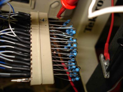
Picture 1 shows the connector that was soldered to the signal cable.
To continue reading: CDC_19_12_2007
Pedestal measurement
A pedestal measurement was done with the old pre-amplifiers not connected to the CDC. The width of the pedestals is around 10 ADC-channels. The width of the pedestals (with common mode noise subtraction) of the whole system is 40 channels. The width of "raw" pedestals is 150 channels


