CDC 20 02 2008
Shaper board
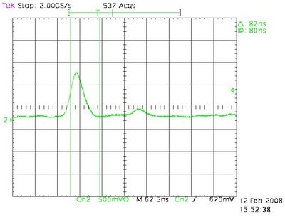
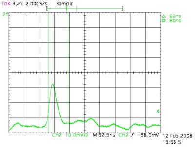
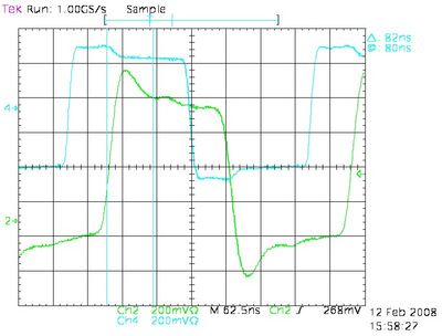
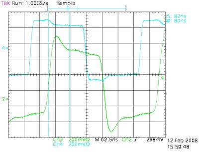
The 16 channel cable preAmp - shaper board arrived today at CMU. Time to take data. After connecting the the cable to the shaper board some problem showed up. Channel 1-2-3 (starting from 0) showed a gain that is a factor of 10 lower than the other channels. Worrisome is that before this behavior already showed up in channel 2 (1 month ago) but after reconnecting the cable it disappeared. Also now, sometimes channel 2 recovers but channel 1 and 3 always stay at the low gain. I saved some scope traces and I believe they are pointing towards a problem close to the 3M connector.
In figure 1.1 a CDC signal can be seen in a good channel (channel 0) in figure 1.2 a CDC signal is shown in a bad channel (ch. 3), notice the difference in the vertical scale.
When injecting a signal in the shaper board no problem is visible. Injecting happens in a different input connector than the 3M one. In figure 1.3 and 1.4 one can see this for a good and bad channel respectively.
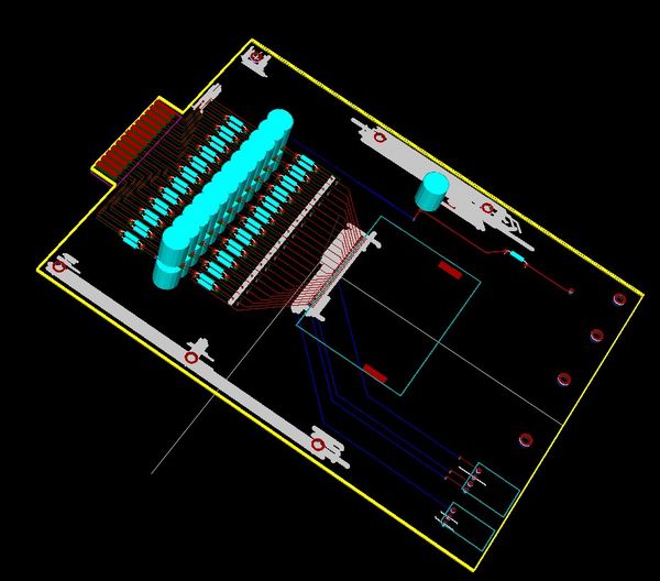
CDC HVB version 3
Can be downloaded here:
A representation can be seen in figure 2.1. Note: this is a 3D representation: the grounding plane is not shown and the (blue) RC devices are meant to be SM (if you look close enough you can see the SM pads) but are not shown as such (there was no 3D representation available for SM devices).
