Status Report on the CDC from 21 November 2007: Noise Studies
Now that all the electronics are mounted outside (see previous status report) it is possible to study the noise. Where should we start? Let's start by taking a reference, in figure 1, one can see a fit pedestal from channel 16 (= channel 8 on the second 200 MHz fADC) taken at the time before all electronics where moved out of the CDC.
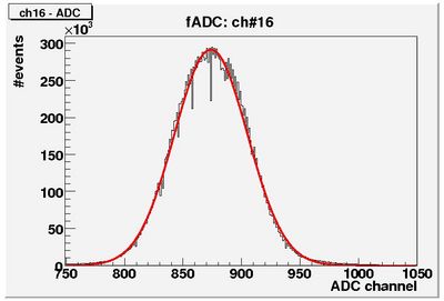
Figure 1: Pedestal of channel 16 before moving out the electronics
One sees a relatively broad Gaussian pedestal. Looking at the signals on the oscilloscope it was observed that the noise more or less looked the same on all channels. In order to subtract this common noise, a very simple common noise (CMN) subtraction algorithm was applied: the average "signal" of all straws, connected to the same fADC, was subtracted from the original signal. In the future a more complex algorithm can be applied, if necessary. The result of this CMN subtraction is shown in figure 2.
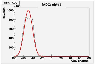
Figure 2: Pedestal of channel 16 before moving out the electronics, CMN subtracted.
Waw, the width of the noise-peak is reduced by almost a factor of 3! One can also see a double peak structure, we'll come back to this later.
Now that we have established a reference, we can talk about the impact of placing the electronics outside the CDC (as will be done in the final design). The first observation was an incredible increase in noise (on the scope, no plots unfortunately). After trying out a lot of configurations it was found that one ground connection from the HV-Distribution-Board (HDB) to the CDC upstream endplate is not enough (it was enough when the HDB was inside the CDC). A couple more connections between the HDB-ground and the CDC-upstream-endplate where made (see picture 1) and again a pedestal measurement was taken. The result of this measurement can be seen in figure 3.
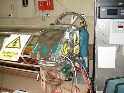
Picture 1: CDC upstream endplate with connections to HDB ground
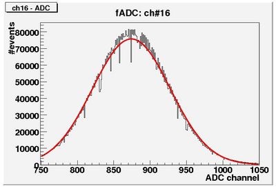
Figure 3: Pedestal of channel 16.
One can see again a broad Gaussian pedestal. After subtracting the CMN there was still this double peak structure for some of the channels. This was investigated by swapping around cables, etc. and it turned out that this was due to some bad LEMO cables going from the differential fan-out to the fADCs. The LEMO cables that are used now are more than 20 years old and have (according to me) a weak spot right behind the connector. We were able to find good ones to work with for now, but new ones will be ordered. The noise peak (CMN subtracted) after changing the LEMO cables can be seen in figure 4.
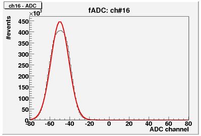
Figure 4: Pedestal of channel 16, CMN subtracted.
There is an increase in the width of the pedestal compared to the situation where the HDB was inside the CDC but after CMN subtraction the width of the pedestals is more or less the same. In order to try to reduce this, 2 more connections between HDB-ground and the CDC-upstream-endplate were made and the result can be seen in figure 5.
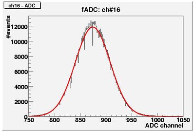
Figure 5: Pedestal of channel 16 with more HDB-ground CDC-upstream-endplate connections.
Yes, the situation improved. If this is all common noise, then the CMN subtraction should take care of it? Apparently this is not the case because the pedestal width also reduces after CMN subtraction compared to the situation before adding two ground connections as can be seen in figure 6.
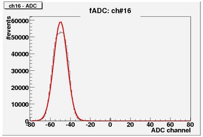
Figure 6: Pedestal of channel 16 with more HDB-ground CDC-upstream-endplate connections, CMN subtracted.
Conclusion: we have to think about proper grounding for the final design.


