CDC 23 01 2008
1 News on the preAmp - Gerard's visit
Today Gerard has started to look at the the CDC setup in order to get the new preAmp working. Here are some things he found:
- ) Our self made differential probe causes the oscillations... they disappear when Gerard uses his own differential probe.
- ) In order to reduce the noise a different LV power supply was used - the ground connections between HVDB (HV Distribution Board) and the CDC were beefed. The LEMO-BNC adaptors were removed. Apparently the type we use at CMU has a known problem (bad grounding).
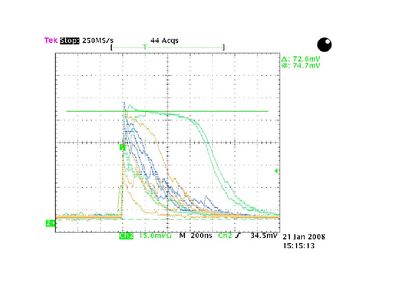
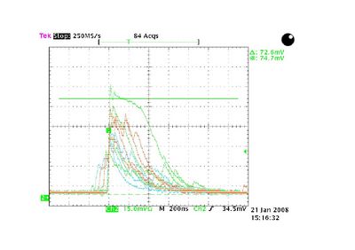
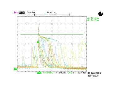
In figure 1.1,1.2,1.3, and 1.4 one can see output signals from the cable (CDC + HVDB + new preAMp + cable) with the CDC at 1950, 2050, 2050, and 1850 V respectively, some signals that saturate can be observed. We used a Ru-106 source.
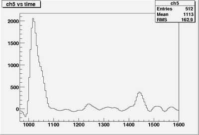
Gerard put the shaper into use and we took some cosmic ray data. In figure 1.5, a signal is shown, in figure 1.6 the same signal is shown but with common mode noise subtraction. Some work still needs to be done.
To be continued...
2 Understanding the drift time spectrum
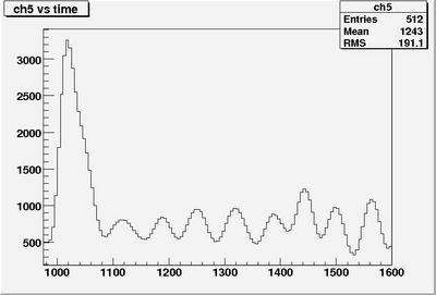
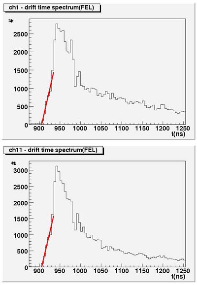
As mentioned on the Collaboration meeting the drift time spectrum shown in figure 2.1 is not understood. One expects a drop-off around 1100 ns = 900 + 200 ns, with 200 ns the maximum drift time in the straw. All measurements is this section are made with the old preAmp and without shaper board.
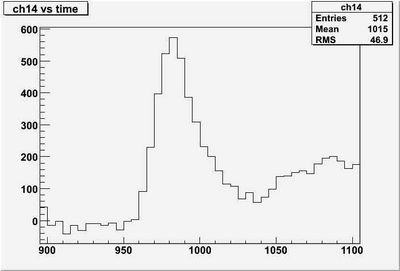
First test was to look at the drift time spectra containing only hits from tracks. These spectra had the same shape. The second test was to look if the fADC was really running at 200 MHz. Therefore it was ran at 100 MHz and a signal with high amplitude was compared with the 200MHz ran fADC. In figure 2.2, the signal taken with the fADC ran at 100 MHz is shown in figure 2.3 the same but now with the fADC ran at 200 MHz. One can see clearly the difference between the two signals.
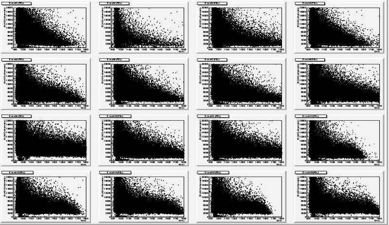
To see if there is a correlation between deposited energy and drift time spectrum correlation plots for all channels where made and shown in figure 2.4. There is no correlation visible that could explain the drift time spectra, although it looks that the tail of the spectrum is dominated by low energy signals.
