Design of an asymmetric monochromator
During the 11/2006 feasibility measurements we used a silicon 111 asymmetrical monochromator. Due to the large Darwin width of the monochromator crystal and the large difference between the Bragg angle of the silicon 111 plane and the diamond 220 plane, the measured diamond rocking curve is much larger than the intrinsic diamond 220 Darwin width, which is around 7 μr. Therefore, for the future measurements, we should consider using a new monochromator which has smaller Darwin width and better match of the refection angle between the monochromator and the diamond reflection plane.
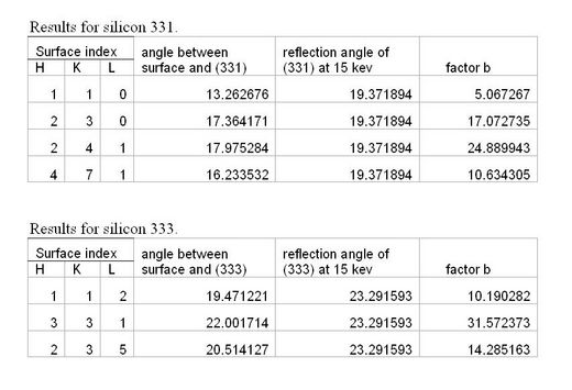
Silicon (331) and (333) both have small Darwin widths and their Bragg angles are quite close to the Bragg angles for diamond 220. Hence, the new monochromator could be built by using the silicon 333 or silicon 331 reflections. Since the distance from the source to the diamond crystal is short, we have to use an asymmetric monochromator to increase beam size and reduce the beam divergence. For some practical reasons, the surface of the monochromator has to be along a plane of the crystal. That means we can not choose an arbitrary angle between the monochromator surface and the reflection plane to design this monochromator. The following table gives the possible planes that could be used to define the surface.
| Table 1. | Possible planes that could be used as the surface plane of an asymmetric monochromator and the corresponding factor b. |
Monte Carlo Simulation
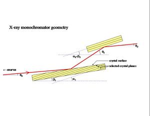
The initial design for the new Si(331) monochromator is shown in the figure at the right. The source lies to the left of the figure. The x axis is the nominal direction of the incident beam. The direction of an incident ray is described by the vertical angle $theta;0 to take into account finite source size effects. The energy of an incident ray is described by the scalar quantity k. After the first reflection in the upward direction, the ray direction is denoted θ1. Following the second reflection downward, the direction is θ2. In the simulation, rays are generated with a flat distribution in k in a window centered on k=15 KeV. The width of the window is chosen to be wide enough (20 sigma) that truncation effects have no visible influence over the distributions of rays transmitted by the monochromator.
- Distance from source to first mono crystal: 10.1 m
- RMS vertical size of source: 0.70 mm
- Angle α1 of monochromator:
The first task is to validate the simulation with some simple plots demonstrating the correct behavior under standard conditions. I begin with a quasi-monochromatic source which I construct in Monte Carlo by selecting only rays with k in the range [14.99999,15.00001] KeV.

