Minutes-8-13-2009
From GlueXWiki
FDC Weekly Meeting
Date: August 13, 2009
Participants: Daniel, Simon, Beni, Brian, Tim, Micah, Eugene, Bill, Mark I.
Next Meeting: August 20, 2009 @ 1:30 p.m.
Contents
General Construction Updates
 - Tim will look into getting us an additional technician to work on the
   FDC system for the next couple of months. We will stand by to this what
   develops.
 - Brian will be off of the FDC project for most of October. This schedule
   should be fine if we can complete detector construction by the end of
   September, which is what we are presently expecting.
 - Mark S. got pulled off of FDC work this week to deal with problem on the
   solenoid. Progress has been noticeably limited this week. We expect him
   back next week, but we will have to see.
 - The parts for the assembly jig on which the detector stack will be
   constructed will be put together as there is time.
 - Bill has begun work on the FDC stack assembly document. The draft will
   be made available after he completes a bit more work on it.  The document
   will be fleshed out during the assembly process with relevant photographs.
 - The composite frames for the two gas windows have been completed. Sealing
   of the I.D. and O.D. of the frames has been completed, with the sealing
   of the bolt holes remaining. The tensioning of the gas windows and the
   lamination to the composite rings will be done as we have time in the next
   couple of weeks.
 - Mark S. made up about 20 of the ground cable pigtails that will be used
   to attach to the cathode planes. More will be made as they are needed for
   the full-scale prototype construction.
 - We should have enough conducting epoxy for the full-scale prototype
   construction, but the full order has gone out. No word on when this will
   arrive.
 - We got an update on the status of the production wire order. The sense
   wire order should arrive by the end of September after the Hall B folks
   completed the first-article acceptance work. We still need to work out
   plans for testing the wire upon arrival. Acceptance work for the CuBe
   wire was not known and we will follow up.
 - A humidity-controlled tent has been set up in EEL 126. We have purchased
   an accurate humidity/temperature monitor. One of the wire frames is now
   in the tent "baking" out.
Wire Frame Update
 - Rich found a number of HV busses that were drawing currents up to about
   1 uA. In order to check if it was humidity related, we put one of the
   wire planes in the humidity-controlled tent on Friday to let it dry out
   over the weekend. It is still in there, but we have not had the manpower
   to check it. We will get to it as we have time. Busses with large
   current draws will be a performance problem and we are going to have to
   find a solution.
 - The last wire plane that needs checking and repairs is P1. This work will
   not happen in the short term as only 3 frames are needed for the
   full-scale prototype and we don't have the manpower to work on this now.
   Three of the frames have been cleaned and had wire repairs done.
 - Rich will provide a write-up on his QA check procedures and make this
   available once it is done.
 - We were worried about torques applied to the preamp card associated with
   the cooling loops. We will most likely improve the bonding strength to
   the wire frame by adding epoxy around the perimeter. We will investigate
   this when we get a bit further in prototype assembly.
 - We need to have a dedicated meeting to design what the schedule for
   work on the Phase 3 wire winding will be. The highest priority for
   work scheduling will be doing work on upgrades of the wire winding
   facility. This includes a better strongback design, the design and
   construction of precision combs, modification to the wire winding
   table, and a list of other items with the system. Stay tuned, more
   to come.
 - The wire frame construction document is located at:
   /u/group/halld/Engineering/PRELIMINARY DOCUMENTS. We will include
   the information on the wire electroplating process shortly.
 - The parts of the jig to use for the wire electroplating operation
   are in our hands. They will be assembled as we find time.
 - Brian received the SEM scans for our wire from the W&M folks. He will
   generate a final QA report with photos and test results for all wires
   when he gets a chance.
Cathode Update
- Progress updates:
* One of our completed cathode boards is really contaminated with
epoxy near the two seams. Bill has worked out a procedure for removing
the epoxy that he is happy with. Bill expects to work on the cathode
board itself once he gets the safety paperwork in place.
* Flatness measurements have been completed on two cathode boards.
We have now established a baseline for comparison that all remaining
measurements can be compared to. The first two cathodes (one with
2 um Cu and one with 5 um Cu) will be used for the first cathode
sandwich for the prototype. We will scan two more boards next week.
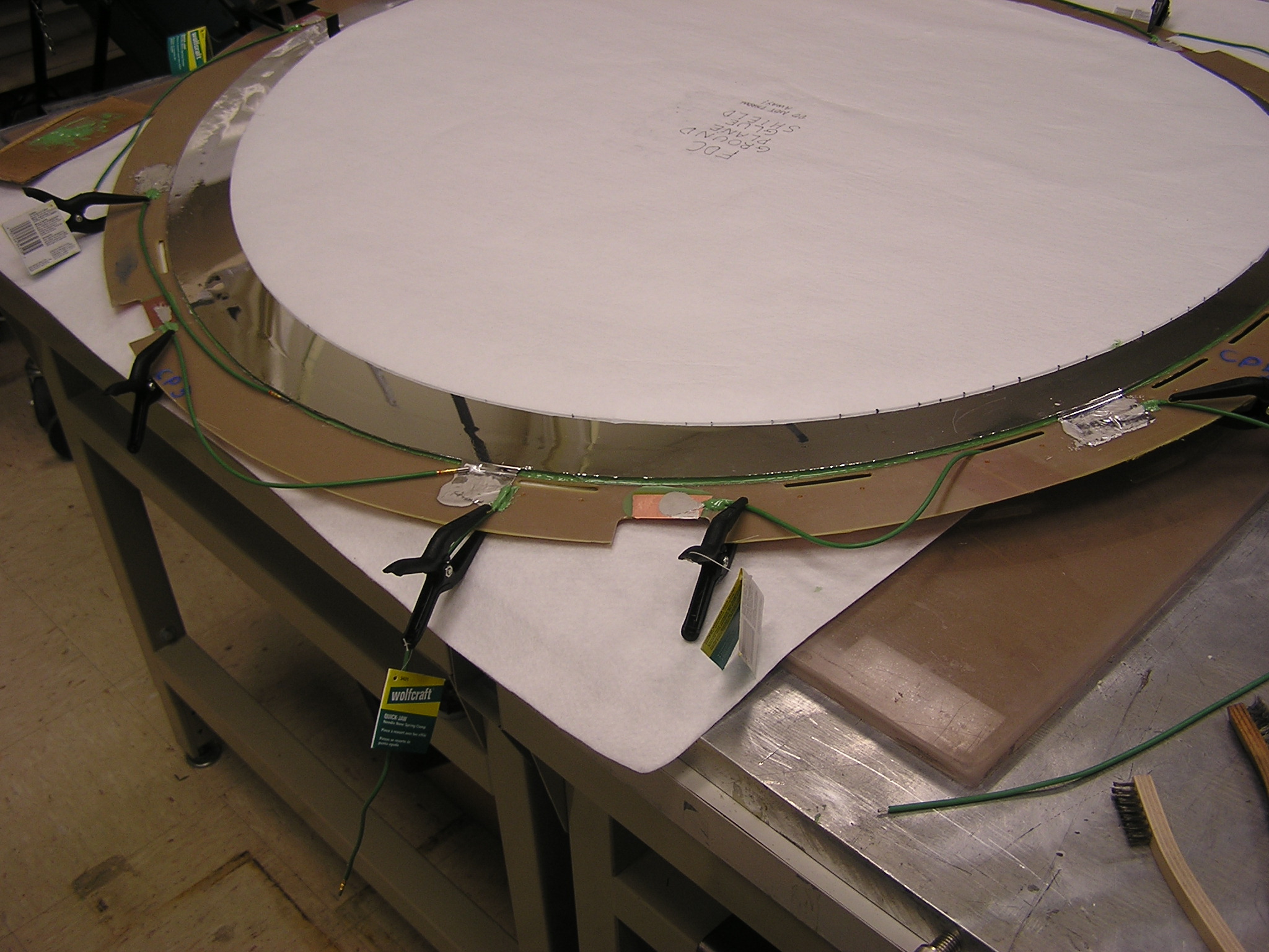
* A ground plane has been attached to the 2 um Cu cathode board and
the ground tabs have been completed on both the cathode boards and
the ground plane. The pigtails have been attached to both with
conductive epoxy. The pigtails will be strain-reliefed with high
bond epoxy. The conductive epoxy will be covered with a sealant to
prevent humidity problems. Brian has been taking lots of photographs
for the construction manual.
* The mating of the 2 um Cu board to the 5 um Cu board for the first
of two cathode sandwiches for the prototype will be done nominally
on Monday or Tuesday of next week.
- We have considered a simplifying design change in the construction of
the cathode sandwiches. Presently on the cathode that we mount the
ground plane to, we have folded over flaps for both the cathode and the
ground plane (see an assembly photograph). We would like instead to leave
the ground plane tabs aligned with the cathode plane tabs and join them
together. This would eliminate 6 ground pigtails from each cathode sandwich.
We would like to construct the second sandwich in this manner. It would be
good to get some feedback from Fernando if he is available.
- We will be investigating strain relief design for the ground pigtails to
be sure that they cannot be over stressed and ripped off.
- Bill is devising a work plan for the prototype construction that he
will give to Chuck to put into a schedule for tracking.
- The Fast Electronics group completed the soldering and initial visual QA
checks on the rigid-flex assemblies. Fernando has designed a system for
electrical QA that should be ready this week. We should follow up with
Armen next week to see if it is ready for use and to find out who will
do the QA checkout.
- Mark S. will begin test soldering of the rigid-flex assemblies to
test cathode pieces to finalize the soldering procedures. He will work
under the direction of Roger and Fernando.
- Bill has been working on the cathode construction document building in
the pictures that are being taken. The current draft of the document
is located at /u/group/halld/Engineering/PRELIMINARY DOCUMENTS. We need
feedback from folks involved in the process to be sure that all steps
are included and accurately detailed.
- We are standing by waiting for information on the PR for the 2-um board
material. We have learned that the order has gone out, but the Japanese
company has still not indicated whether they will fill the order. A
second company that can produce the board material has been identified.
Roger has been in contact with the U.S. representative of this company
and believes that we will have an answer by the end of this month.
- Roger needs to prepare a document for QA/stuffing/cleaning for the
cathode boards and a similar document for the cathode daughter
boards and ground boards.
Cooling System Tests
 - Fernando is in the process of writing up the results from his cooling
   system studies.  Stay tuned for the GlueX note. He indicated that he
   is back to work on this document and it should be done shortly.
Cosmic Ray Test Stand
 - Beni is continuing work to setup the cosmic ray telescope and test
   system in EEL 126. He is now battling a noise source somewhere broadcasting
   at about 30 kHz. He has also found some isolation transformers to give
   him some clean power sources. It looks like one important source of noise
   (among several) is the CAEN HV supply that we are using for the hodoscope
   scintillators.
 - We still have some mysterious behavior with the small-scale prototype
   response with wiggles in the X vs. Y distributions that need to be
   understood. Beni is now trying to reproduce the "picket fence" plots from
   the small-scale prototype to get back to where Simon was last year. He is
   getting close.
 - Beni has started a bench test plan for the full-scale prototype and
   is presently working on it after incorporating feedback. The current
   information is contained on the FDC wiki page under the heading
   "FDC test cosmic ray test stand".
 - The parts for the support/rotation of the full-scale prototype in the
   cosmic ray stand will be assembled as we have time.
Work List
 - The FDC short-term work list has been posted on the FDC web site.
   This is continually being updated and DSC welcomes any feedback or
   comments from the group.
Minutes prepared by Daniel. Send any comments or corrections along.