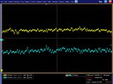
Noise studies
Contents
[hide]Intro
The thermocouples attached to the small CDC prototype increased its propensity for e-m pickup; our objectives were to identify this in the data amplitude and energy spectra and reduce it if possible. Reducing the ambient e-m pickup allowed the noise created by the thermocouple measurements to be seen more clearly. The full history of this is given in Full story below.
Present setup
Modified HVB and new preamp (preamp4).
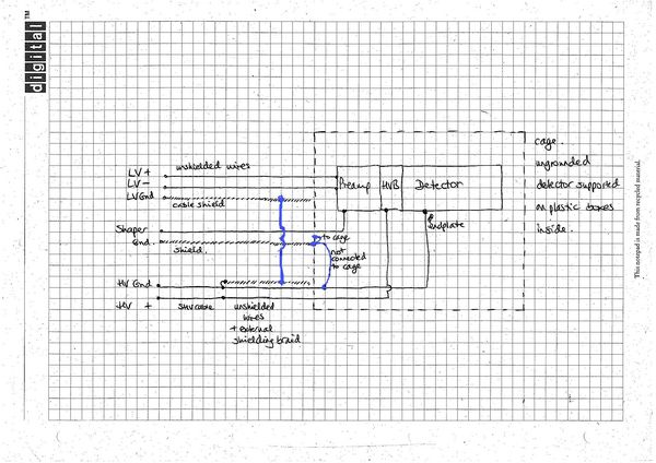
LV supply: HP 6216A, using + and -, ground connected only to a mesh shield covering the cable
HV supply: Vern-Kiebler 6900 [spec sheet]
Mains: power supplies, oscilloscope and thermocouple (if used) are plugged into mains strip mounted on the DAQ rack; the PC recording thermocouple measurements is not.
DAQ: NIM and VME crates are in one rack
Cage: the detector is inside a small mesh box (Faraday cage) [photos of caged prototype]
Cables: The SHV cable is connected to 2 small wires taking HV and ground to the CDC, this junction is made just outside the entrance to the Faraday cage; the short wires are 10-20cm long. The LV cable was unshielded so we added shielding braid connected to the LV supply ground at one end and ending just outside the cage. (The shielding did decrease the pickup.) See below for schematic for unmodified HVB.
Thermocouples: the control unit has been disconnected and removed; the wires remain inside the cage.
Noise measurements are as follows:
| pickup amplitude (mV) (2100V, 50/50 premix) +/- 1mV approx | |||
|---|---|---|---|
| Straw 1 | Straw 16 | ||
| Starting point, no new grounds | 7.5 | 13 | |
| HV ground = LV shield (cage end) | 4 | 7.5 | |
| HV ground = LV shield = shaper shield | 4 | 5.5 | |
| HV ground = LV shield = shaper shield = cage | 3.5 | 6 | |
| HV ground = LV shield = cage | 3 | 5.5 | |
| HV ground = cage | 7 | 20.5 | |
| Cage removed, HV ground = LV shield | 4 | 8 | |
In the configuration adopted with HV and LV cable shields connected to both HV ground and the cage, typical pedestal width is 13-15 channels.
This is a little higher than with the unmodified HVB, could be due to the HVB swap or to the thermocouple wires, which all now have one end free, but inside the cage.
Conclusions
- The thermocouple wires increased e-m pickup.
- The thermocouple controller caused e-m noise.
- The Faraday cage reduced pickup, particularly from the thermocouple controller - 40MHz pickup was reduced from 40mV to 14mV.
- Shielding the LV supply wire and grounding this shield to the HV ground also reduced pickup. When the thermocouple controller had been deactivated, this grounding was almost as effective at reducing pickup as the Faraday cage.
- Our noise levels are now very low - 6 mV amplitude inside Faraday cage, 8mV outside. Current fADC range is 550mV.
- Thermocouple wires need to be at least 12cm away from the ends of the anode wires - the pickup increased with straws closer to the thermocouples.
Postscript (thermocouple removal)
I measured pickup amplitude with the scope before and after covering the thermocouples with shielding braid, grounded to the HV ground, and removing them entirely. In each case the HV and LV cable shields are connected to HV ground at the prototype end, as before.
| pickup amplitude (mV) (2050V, 50/50 mix) +/- 1mV approx | |||
|---|---|---|---|
| Straw 1 | Straw 16 | ||
| No cage, thermocouples unshielded | 5 | 10 | |
| No cage, no thermocouples | 4 | 8.5 | |
| pickup amplitude (mV) (2050V, 50/50 mix) +/- 1mV approx | |||
|---|---|---|---|
| Straw 1 | Straw 16 | ||
| Prototype inside cage, thermocouples extending outside | 4.5 | 9 | |
| Prototype inside cage, shielded thermocouples extending outside | 3.5 | 6 | |
| Prototype inside cage, no thermocouples | 4 | 6 | |
Full story
Beginning
After attaching the thermocouples - 3 24" wires leading to a control unit - to the small CDC prototype we observed that the post-shaper pedestal width (calculated as standard deviation on pedestal mean for first 100 timebins in 1000 events) was largest in the straws nearest the top of the prototype - it showed a steady increase moving up the detector whereas previously the widths had all been similar. At this point it went from approx 11ch (lowest row of straws) to 18 ch (highest row) (run 30765, 13 June 2010, ADC range ~ 550mV). The thermocouple wires were attached to the gas plenums at the top. After moving the thermocouple wires around and observing the signals on the oscilloscope we realised that the thermocouple wires were picking up e-m noise and passing this on to the nearest straws.
This pickup had amplitude ~ 22mV for straw 16 (top row of 6), 16mV in straw 12 (5th row), 10mV in straws 8 and 4 (rows 3 and 2) and hardly noticeable at 8mV in straw 1 (row 1). The nearest thermocouple wire is approx 3cm from the end of straw 16 and 12cm from straw 1.
As well as picking up ambient e-m noise (mostly 4-5Mhz) the thermocouple control unit also contributed some noise of its own (350ns bursts of 40Mhz, up to 40mV, repeated at approx 88Hz). When taking Fe55 data the ADCs are triggered on signals in straw 15 and its internal threshold was increased x3 in order to eliminate the noise-only events.
Noise reduction
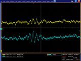
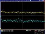
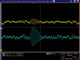
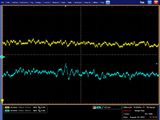
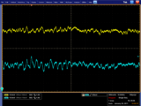
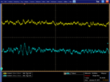
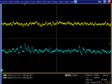
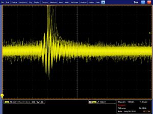
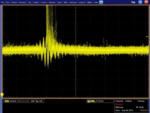
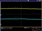
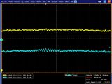
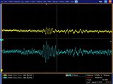
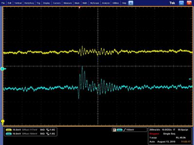
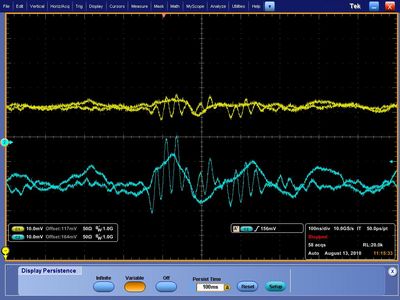
At this point we discovered that connecting the HV ground to the shielding (RHS pic) covering the preamp-shaper signal cable reduced the pickup from ~22mV to ~15mV. The HV ground is also connected to the detector endplate. The following oscilloscope traces are for straw 16, which shows the largest amount of pickup, with the thermocouples switched off. The RHS pic is after connecting the preamp signal cable shielding to the HV ground. Both pics also show some cosmics.
Faraday cage
We moved the detector and all the thermocouple kit (including unplugged power cable) into a small mesh box to act as a Faraday cage; this reduced the pickup noise to 15mV in straw 16 and the pedestal width to 9-11 channels, for all straws. At this point connecting the HV ground to the shielding covering the preamp-shaper signal cable reduced the pickup to 10mV but grounding the cage separately increased the pickup to 23mV (more details follow later). The HV, LV supplies and scope were all plugged into the power distribution strip running down the back of the electronics rack which holds the NIM and VME crates.
HV supply
Some oscillation in the post-shaper signal originates from the Vern-Kiebler HV supply. [spec sheet] This is also visible in the low-voltage test output from the front of the unit as +/- few mV 27kHz square wave. The peak to trough variation in the post-shaper signal is around 10mV but away from this the signal width is 4mV.
We switched to a Bertan 215 HV supply which cut the pedestal sigma down to 5 to 7 channels... but also decreased the tracking efficiency by 50%.
So we returned to the Vern-Kiebler unit.
Adding cable shielding
The LV supply is a HP6216; the + and - leads go to the preamp through unshielded cable; the ground was not used. Pickup was reduced slightly when we moved the LV supply unit inside the cage (its output wires were unshielded) but the trailing cables were undesirable and so we returned it to the DAQ rack and added shielding braid outside the cables. This braid was grounded to the LV ground, but making this connection made no observable difference to the pickup. Moving the LV unit back to the rack (with the shielding) added 1mV to the pickup.
The SHV cable was connected to the thin wires which then connected to the detector's HV board. We added shielding braid to cover these and connected it to the HV ground at the end of the SHV cable. Linking this shielding braid to the LV shielding braid close to the cage decreased the pickup noise in straw 16 from 14mV to 8mV and linking it to the cage as well decreased it further to 3.5mV amplitude. At this point no further reduction was obtained by linking the preamp-shaper cable shield to the HV ground :-)
Final setup with unmodified HVB
LV supply: HP 6216A, using + and -, ground connected only to a mesh shield covering the cable
HV supply: Vern-Kiebler 6900 [spec sheet]
Mains: power supplies, oscilloscope and thermocouple (if used) are plugged into mains strip mounted on the DAQ rack; the PC recording thermocouple measurements is not.
DAQ: NIM and VME crates are in one rack
Cage: the detector is inside a small mesh box (Faraday cage) [photos of caged prototype]
Cables: The SHV cable is connected to 2 small wires taking HV and ground to the CDC, about 1m long. At the connection point we added shielding braid (taped to the connector to ground it) to cover the wires from that point until just outside the cage. The LV cable was unshielded so we added shielding braid connected to the LV supply ground at one end and ending just outside the cage. (The shielding did decrease the pickup.)
Noise measurements are as follows:
=====Thermocouples inactive===== - thermocouple kit unplugged and inside cage - nearest thermocouple wire is approx 3cm from end of straw 16 and 12cm from straw 1
| 5Mhz pickup amplitude (mV) (2100V, 50/50 premix) | |||
|---|---|---|---|
| Straw 1 | Straw 16 | ||
| Starting point, no new grounds | 8 | 14 | |
| HV shield = LV shield (cage end) | 5 | 7.5 | |
| HV shield = LV shield = shaper shield | 4 | 5 | |
| HV shield = LV shield = shaper shield = cage | 2.5 | 4 | |
| HV shield = LV shield = cage | 2.5 | 3.5 | |
| HV shield = cage | 5.5 | 15.5 | |
Thermocouples active
Activating the thermocouple controller adds to the 5MHz pickup but also contributes a 40MHz signal of its own.
| Straw 1 5MHz pickup amplitude (mV) | Straw 16 5MHz pickup amplitude (mV) | |
|---|---|---|
| Control box inside cage | ? | 20 |
| Control box moved outside and semi-screened | 2 | 7 |
| Straw 1 40MHz pickup amplitude (mV) | Straw 16 40MHz pickup amplitude (mV) | |
|---|---|---|
| Control box moved outside and semi-screened | 4.5 | 13.5 |
In the configuration adopted with HV and LV cable shields connected to both HV ground and the cage, typical pedestal widths are 9-11 channels (thermocouples off) and 9-13 channels (thermocouples on).
At the beginning of this saga the 40MHz thermocouple noise amplitude in straw 16 was 40mV (no cage).
This brings us up to date with Present Setup above.
