Results for the 20 micron diamond
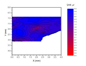
The two plots below show a colour-coded contour map of the rocking curve width for the 20 micron thick diamond crystal. The diamonds are approximately square 6mm x 6mm. The X-ray beam used to produce these rocking curves was approximately 3mm x 15mm (3mm is perpendicular to the rocking axis) so the images are cut by the beam dimensions along the rocking direction.
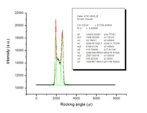
The following rocking curves measured at isolated pixels of the CCD camera at some interesting locations.
The minimum rocking curve width for the 20 micron diamond is around 30 μr. The measured rocking curve width is broader than the true rocking curve with of the diamond crystal due to the instrumental broadening. The main source of the instrumental broadening is the X-ray beam divergence. For an isolated pixel, the beam divergence is ~15 μr. We used a (+,-) crystal set-up for the monochromator crystal and the diamond crystal. Since the diffraction angles are different, this setting is not truly non-dispersive. The additional rocking curve width from dispersion is ~9 μr. Taking the above 2 contributions into account, the diamond rocking curve width should be less than ~24 μr.
Another possible reason for the rocking curve broadening is the curvature of the diamond crystal. The adhesives used for mounting and the marks on the crystal surfaces are the possible sources that could introduce stress to the crystal and the crystal are deformed by stress. If the crystal diffraction plane is all the same at different crystal locations, the measured rocking curve should have the same rocking curve peak position (if the d spacing is all the same for different positions). The rocking curve peak positions recorded by different pixels of the camera are quite different. This means the 20 micron diamond crystal is severely deformed by stress.
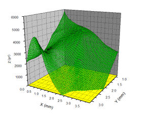
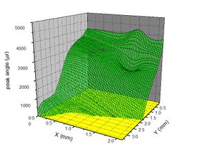
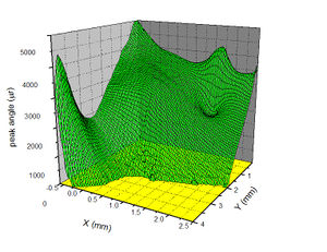
The following are two graphs showing the rocking curve peak positions varying with pixel positions. Note that the length scales on the two axes are not equal, so they are not simply 90° rotations of each other. Nevertheless one can see how one is transformed into the other by rotating and clipping.
| . | . |
If we assume the rocking curve peak position shift is caused only by the curved Bragg plane, we can use the peak shifts to reconstruct the crystal shape. In order to reconstruct the diamond crystal shape, we need at least two orthogonal rocking curve scans. Then we have a question, how to locate the same point on the sample from the images taken at different settings? The first reason for this is the image taken at different setting has a different χ angle, which means the image has been rotated by a certain angle. Secondly, because the CCD camera is perpendicular to the diffracted x-ray beam, the image height is smaller than the crystal height, so we need to rescale the image in vertical direction. The alignment error could be another reason for the need of a translating and rotating transformation. In order to do this transformation, we need at least 2 characteristic points to determine the parameters we need. Probably we also need a third one to check the results. The characteristic points should be taken at easily distinguishable points, such as corners.
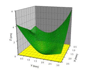
The following is a graph showing the reconstructed diamond crystal shape extracted using the rocking curve peak shift information. It was obtained by integrating the rocking curve peak shifts from the (-2 2 0) scan along the short (x) direction. Peak shifts for a single row of pixels from the (2 2 0) scan was used to obtain the starting value for each column. The initial slope was set to zero (low x, low y corner). Because the vertical X-ray beam size is smaller than the crystal size, we do not have enough information to reconstruct the whole crystal.
By using the above reconstructed crystal shape, we can calculate the peak angle for the (2 2 0) axis. Compare this calculated peak angle with the peak angle measured by another scan(scan 214), we found the calculated peak angle has almost identical shape with the measured peak angle across the crystal face within the same area on the crystal, and this confirms that the crystal shape has been reconstructed correctly.

