Test Plan and Setup in Hall A
From GlueXWiki
The Draft Test Plan to Study Radiation Damage to SiPMs in Hall A
Contents
- 1 Test Plan
- 2 Test Log
- 2.1 2010 Mar 17
- 2.2 2010 Mar 18
- 2.3 2010 Mar 19
- 2.4 2010 Mar 21
- 2.5 2010 Mar 22
- 2.6 2010 Mar 23
- 2.7 2010 Mar 24
- 2.8 2010 Mar 25
- 2.9 2010 Mar 26
- 2.10 2010 Mar 29
- 2.11 2010 Mar 31
- 2.12 2010 Apr 1
- 2.13 2010 Apr 5
- 2.14 2010 Apr 6
- 2.15 2010 Apr 7
- 2.16 2010 Apr 16
- 2.17 2010 Apr 18
- 2.18 2010 Apr 20
- 2.19 2010 Apr 22
- 2.20 2010 May 4
- 2.21 2010 May 5
- 2.22 early test data
- 3 Test Condition
- 4 Data
- 5 Results
- 6 Facts and Conclusions
- 7 1×1 mm2 SiPM Test in Hall A
Test Plan
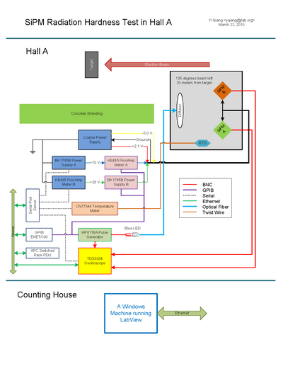
System Diagram and Floor Plan
Device List
- Control Computer: transversity.jlab.org: (129.57.164.28)
- GPIB over IP: GPIB-ENET/100: agpib.jlab.org (129.57.192.73)
- Serial Port Server: ESP904: portservha50.jlab.org (129.57.192.78)
- USB over IP: AnywhereUSB/5: ausb.jlab.org (129.57.192.75)
- Oscilliscope: TDS3034: dosci.jlab.org (129.57.192.77)
- Power Outlet: APC Outlet Control: hlauser:hlauser@hareboot12.jlab.org (129.57.192.76)
- Outlet 1: Pulse Generator
- Outlet 2: Temperature Box
- Outlet 3: Oscilliscope
- Outlet 4: GPIB over IP
- Outlet 5: Power Supply for Hamamatsu Unit
- Outlet 6: Power Supply for SensL Unit
- Outlet 7: Picoamp Meter
- Outlet 8: Serial Port Server
- USB to Serial HUB: ComHUB
- Serial 1 (COM5): Power Supply for Hamamatsu Unit
- Serial 2 (COM6): Power Supply for SensL Unit
- Serial 3 (COM7): Oscilliscope
- Serial 4 (COM8): Temperature Box
- Picoamp Meter x2: Keithley-485 (GPIB)
- GPIB Address: 1 (Hamamatsu); 2 (SensL)
- Pulse Generator: HP-8116A (GPIB)
- GPIB Address: 4
- Power Supply x2: B&K-1787B (RS232)
- Temperature Meter: CN77544 (RS232)
Power Connection and Settings
- Power Cable Color Code
- Black: Ground
- Yellow: -5.0 V
- Red: +2.1 V
- Blue: Hamamatsu Bias Voltage
- Green: SensL Bias Voltage
- SiPM Bias Voltage Correction vs Temperature
- Hamamatsu: 56 mV/C (70.27 at 20 C)
- SensL: 23 mV/C (28.6 at 20 C)
EPICS Variables
Hall A Beam Line IOC: iocha5.jlab.org [129.57.188.5]
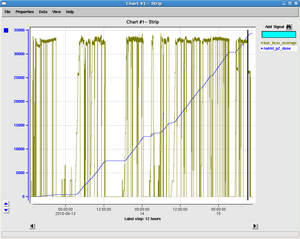
- hac_bcm_average: Hall A beam current (uA)
Hall A Cryo Target IOC: iocha13.jlab.org [129.57.188.29]
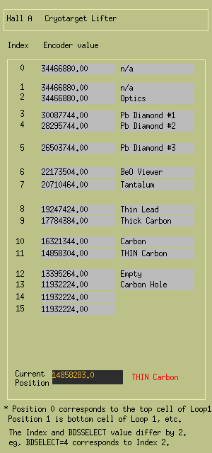
- haBDSPOS.VAL: Hall A cryo target position (encoder value)
MCC general IOC: 129.57.255.4
- rad44_p2: Neutron dose [mRem/hour]
- rad44_p2_dose: Accumulated Neutron dose [mRem]
- rad44_p1: Gamma dose [mRem/hour]
- rad44_p1_dose: Accumulated Gamma dose [mRem]
Test Log
2010 Mar 17
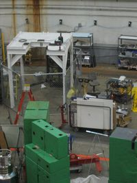
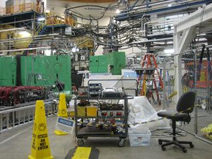
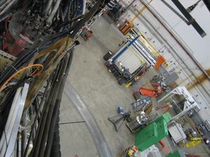
- Photos of SiPM test setup.
- All Hardware intrustruments have been connected.
- The SiPM box is put on top of the cryo target parking support which is at about 135 degrees to the left side of the beam and 20 meters away from the target.
- The real time neutron counter is put right next to the SiPM.
2010 Mar 18
- Have all the remote communication working properly.
- Other than the oscilloscope, Labview programs to all the rest devices are ready.
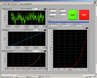
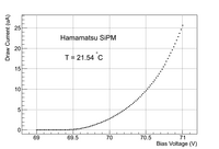
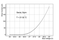
- Did first measurement of the correlation between the draw current and the bias voltage.
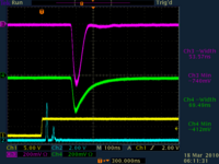
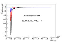
- Signals on Oscilloscope with 70.5V on Hamamatsu and 28.5V on SensL are shown as well.
2010 Mar 19
- Finished Oscilloscope initialization program, the readback program is done as well but not quite stable
- Increase the pulse frequency to 1.0 kHz, here is the final configuration for the pulse generator
* Direct DC couple to the LED
* Frequency: 1.0 kHz
* Width: 8.0 ns
* High Level: 5.0 V
* Low Level: 0.0 V
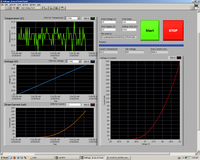
- Tested the draw current corresponding to the voltage level and recorded the oscilloscope signals (average of 128 waveforms)
- Removed both SiPMs from the box for Hall closing.
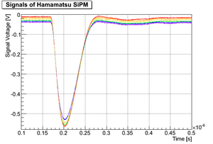
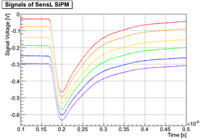
- SiPM signal shape vs bias voltage
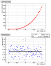
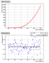
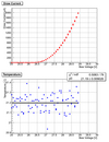
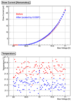
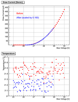
- Draw current vs bias voltage
- SiPM signal amplitude vs draw current as a function of bias voltage. From the plots, we can have some sense of the signal to background ratio.
2010 Mar 21
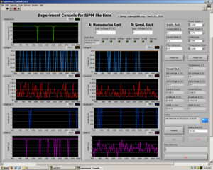
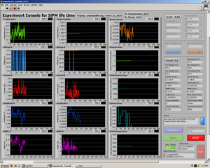
- Finished first version of the Central Control VI, change all serial communication timeout to be 1 second
- Stress test
2010 Mar 22
- Stress test failed, system won't run VI after rebooting. Maybe it's time to rebuilt the XP system on the computer
2010 Mar 23
- Brought transversity.jlab.org to CC for a system rebuilt
- At the mean time, upgraded the Central Control VI to version 2 with a more responsive interface and better timing control.
2010 Mar 24
- CC rebuilt the XP System
- Installed all necessary software, all devices are up and running well
- Changed GPIB timeout to be 1 second, should not have any timeout problem
- Stress test with Central Control VI without writing file to the disk :S
2010 Mar 25
- Modified the algorithm to initialize the VISA resource.
- New stress test passed 30000 readings!!!!
2010 Mar 26
- AGPIB and DOSCI lost connection at around 12:30AM when MCC tuning beam in the Hall. Rebooting solved the problem. More shielding may be required.
2010 Mar 29
- Added additional shielding in front of the instruments
2010 Mar 31
- EPICS readout configured
2010 Apr 1
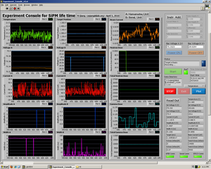
- Updated Control VI to v4 with intregrated EPICS readout
2010 Apr 5
- Updated Control VI to v5, new features added
- independent readouts from GPIB, Serial and EPICS
- added communication status indications
- added plot history feature
2010 Apr 6
- Calibrated RTD temperature sensor using an ice-water mix
- Offset is 0.185 +- 0.005 degrees
- Therefore, nominal temperature in Hall A is 21.0 degree, so the bias voltages for two SiPMs are:
- 70.33 V for Hamamatsu
- 28.62 V for SensL
2010 Apr 7
- Added Temperature Feedback to Bias Voltage
- Temperature averaged over 10 minutes, statistical fluctuation < 0.01 degrees
- Voltage adjust step: 1 mV
- Voltage_Hamamatsu = 70.27 + 0.056*(T-20)
- Voltage_SensL = 28.6 + 0.023*(T-20)
2010 Apr 16
- Hall A finally took the first production run
2010 Apr 18
- The Hamamatsu power supply lost communication. Could not be fixed through multiple remote reboot. Probably caused by radiation damage :S
- The neutron dose meter can only read 3 digit, once the reading is over 100000, it won't be very easy to accurately trace the dose, needs to be reset.
2010 Apr 20
- Neutron probe has been reset
- Test in Hall A started from 18:00
2010 Apr 22
- Beam stopped at 09:00
- Test in Hall A finished at 09:00
- Draw current: 200 uA for Hamamatsu and 1600 uA for SensL
- Leave the all the instruments in tunnel with temperature about 21 C
2010 May 4
- Move all the instruments to ARC Room 628 at 15:00
- Room Temperature at Room 628 is about 22 C
2010 May 5
- Started Annealing test from 18:00 in Room 628
- Draw current: 135 uA for Hamamatsu and 1120 uA for SensL, both get lowered
early test data
- 20100318 Pulse Frequency: 500 Hz
- 20100319 Pulse Frequency: 1.0 kHz
Test Condition
- Time: 04/20/2010 12:30 PM
- Location: Hall A beam left
- Initial Dose
- Neutron (rad44_p2) 18.4 mRem
- Gamma (rad44_p1) 61900 mRem
- Radiation Chips
- Neutron Rod: serial# 2A01 close to SiPM
- TLD: serial# 9597, close to SiPM and rad44_p2
- TLD: serial# 9598, close to rad44_p1 at entrance
Data
Pre-Rad Measurement
- Voltage vs Current scan done
- Hamamatsu: 20100420_132141_VICurve.txt
- Hamamatsu: 20100420_132531_VICurve.txt
- SensL: 20100420_132531_VICurve.txt
- SensL: 20100420_132531_VICurve.txt
Beam ON Test
- Oscilloscope Snapshot #1: 20100420_135400_CHx.txt
- Oscilloscope Snapshot #2: 20100421_014000_CHx.txt
- Oscilloscope Snapshot #3: 20100421_091100_CHx.isf
- Oscilloscope Snapshot #4: 20100421_182200_CHx.isf
- Oscilloscope Snapshot #5: 20100422_015300_CHx.isf
- Oscilloscope Snapshot #6: 20100422_102700_CHx.isf
- Dataset #1: 20100420_140630.txt
- Stopped due to GIPB problem
- No production
- Dataset #2: 20100420_182713.txt
- Long run with production started
- 22:40:30 - 01:46:10 oscilloscope not updating
- Stopped due to GPIB problem
- Dataset #3: 20100421_091253.txt
- Stopped due to EPICS problem
- Dataset #4: 20100421_105132.txt
- HV OFF at 10:59:00 to test radiation damage with bias voltage OFF
- Stopped to turn bias voltage back ON at 18:21:00
- Dataset #5: 20100421_182344.txt
- New dataset with bias voltage ON
- Stopped due to GPIB problem
- Dataset #6: 20100422_015736.txt
- Stopped due to GPIB problem
- Dataset #7: 20100422_091215.txt
- Beam OFF
- oscilloscope not updating
Post-Rad Measurement
- Voltage vs Current scan done
- Hamamatsu: 20100422_105000_VICurve.txt
- Hamamatsu: 20100422_105334_VICurve.txt
- SensL: 20100422_105732_VICurve.txt
- SensL: 20100422_110249_VICurve.txt
Results
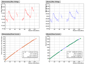
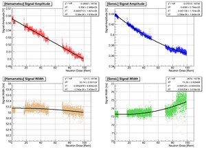
- Change of draw Current and signal shape at working condition as a function of radiation
- Comparison of VI response before and after radiation
- Signals recorded by oscilloscope show the effect of radiation on amplification: red (initial) -> violet (final)
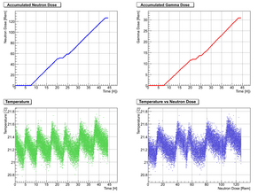
- If we take the dose to fluence coefficient of 1 MeV Neutron: 400 pSv.cm2 = 4x10⁻⁸ rem.cm2 (1 mrem/H -> 6.9 neq/s/cm2), we have the following plot
Aneeling of Radiation Damage
Facts and Conclusions
- Hall A radiation level is extremely high during P-REX experiment: 50uA on 0.5mm Pb target (9% radiation length).
- A lot of energy dumped to the 2 pieces of collimator behind Pb Target: estimated 1 kiloWatt total power dissipated on them.
- The neutron dose rate before the collimator installed was 1.55 rem/H with 45 uA beam on Pb target. After the collimator was installed, the dose rate during the SiPM test was 1.35 rem/H with 50 uA beam. Therefore the tungsten collimator did not significantly change the radiation level.
- Radiation causes draw current to increase no matter whether bias voltage is applied.
- Hamamatsu: starting from 8 uA, 5 uA/Rem
- SensL: starting from 155 uA, 40 uA/Rem
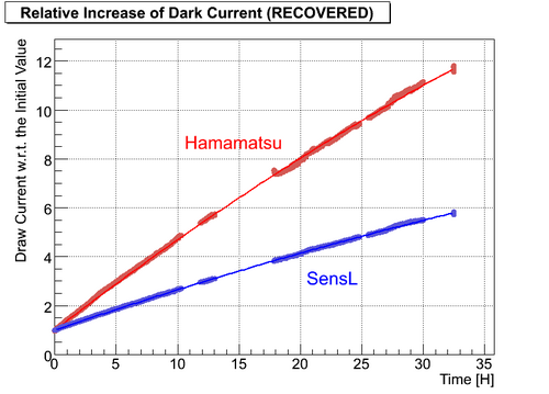
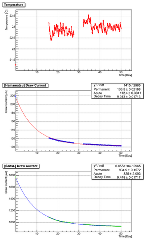
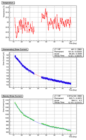
- The dark current from both SiPM samples recovered by about 50% with time constant of 10 days
- Taking the bias voltage adjustment into account, the dark current has an exponential relation to the ambient temperature:
- I(dark) ~ exp(a*(T-T0))
- a for Hamamatsu: 0.061±0.003/C
- a for SensL: 0.047±0.002/C
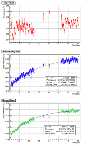
- Radiation slowly affects the amplification of SiPM but has no effect on the signal width, even though, the drops of the gain get fully recovered afterward.
- Report to GlueX meeting (2010/05/10): link to docDB
- Dark rate measurement shows a increase of noise level consistent with the increase of dark current:Carl's report
- I(dark) ~ Sigma(pedestal)^2
1×1 mm2 SiPM Test in Hall A
Test Condition
- Same location as previous 3x3 SiPM test: 135 degrees, 20 meters
- Not powered
- Temperature: ~ 21.3 degree C
- SiPM information:
- Type Number: S10362-11-050C
- Serial Number: 1260
- Vop: 71.54 V
- M: 7.50e+5
- Dark Rate (0.5 p.e.): 536 kcps
- Dark Rate (1.5 p.e.): 44 kcps
- X-talk: 8.2%
- PDE (lambda = 490 nm): 36.5%
- At 25 degree C
Initial Neutron Dose 2010/06/11 11:20 AM
- rad44_p2_dose: 0 Rem
Final Neutron Dose 2010/06/15 10:00 AM
Test Result
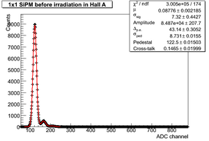
- ADC dark spectrum before irradiation
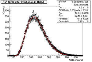
- ADC dark spectrum post irradiation
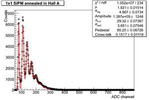
- ADC dark spectrum 2 months later
- Note
- The pre-amplifier used in the first two tests (before and post) was from Stepan with a total gain of 105 while during the last test (anneal) the pre-amplifier from Fernando was used with a gain of 65.
- Permanent damage increases dark rate by 21
- Permanent damage increases dark current by 18: Carl's measurement
- Cross-talk: 15%
