Difference between revisions of "Light Guide Information"
From GlueXWiki
(→Quick transmission measurement) |
(→Quick transmission measurement) |
||
| Line 26: | Line 26: | ||
=== Quick transmission measurement=== | === Quick transmission measurement=== | ||
| − | * We took a quick look at the transmission through the light guide using the procedure shown in the [[Media:Guides testing Apr6.pdf | Test Setup Figure]]. Used a #20 light guide. Dimensions are approximate as the setup was jury-rigged for the occasion. | + | * We took a quick look at the transmission through the light guide using the procedure shown in the [[Media:Guides testing Apr6.pdf | Test Setup Figure]] with the help of Sasha and Vitaly Baturin. Used a #20 light guide. Dimensions are approximate as the setup was jury-rigged for the occasion. |
* Pinhole test: Check bulk attenuation. Used two 1mm2 pinholes separated by the height of the light guide (8 cm). Measured currents were 3.2 nW/cm2 (no light guide) and 3.4 nW/cm2 (with light guide), indicating that there was no visible bulk attenuation through the light guide over the 8 cm. Note that the small aperture reduced the light to extremely low levels; background levels were on the order of about 0.3 nW/cm2. | * Pinhole test: Check bulk attenuation. Used two 1mm2 pinholes separated by the height of the light guide (8 cm). Measured currents were 3.2 nW/cm2 (no light guide) and 3.4 nW/cm2 (with light guide), indicating that there was no visible bulk attenuation through the light guide over the 8 cm. Note that the small aperture reduced the light to extremely low levels; background levels were on the order of about 0.3 nW/cm2. | ||
* Transmission test: Limited entrance angles to the light guide to less than 17 degrees(side) and 23 deg (corner) using a 1x1mm2 and 12x12m2 square apertures separated by 2 cm. This corresponds to a maximum angle in the light guide of 15 degrees (maximum angle inside the fibers is 27 degrees). The light exiting the collimation system was determined by placing the light sensor directly over the 12x12 cm aperture (18.5 nW/cm2). The light through the light guide was determined by placing the light guide base over the 12x12 aperture and taking a reading of light at the top exit (10 nW/cm2), giving a transmission of about 54%. Within the accuracies of the measurements, we confirm the expectation for transmission. | * Transmission test: Limited entrance angles to the light guide to less than 17 degrees(side) and 23 deg (corner) using a 1x1mm2 and 12x12m2 square apertures separated by 2 cm. This corresponds to a maximum angle in the light guide of 15 degrees (maximum angle inside the fibers is 27 degrees). The light exiting the collimation system was determined by placing the light sensor directly over the 12x12 cm aperture (18.5 nW/cm2). The light through the light guide was determined by placing the light guide base over the 12x12 aperture and taking a reading of light at the top exit (10 nW/cm2), giving a transmission of about 54%. Within the accuracies of the measurements, we confirm the expectation for transmission. | ||
Revision as of 13:27, 7 April 2011
Contents
Light Guide Collection
References to Simulation
- Path to repository for GEANT3 routines (Elton):
- The code I have used to compute light guide collection acceptances for the Bcal (See GlueX-doc-1077 and GlueX-doc-959) are stored under svn at svn ls https://halldsvn.jlab.org/repos/trunk/home/elton/geantguide The original code came from Blake (UofR) and modified to suit my application. If anyone wants to use it they should contact me for more details. My own suggestion to begin light guide simulations would be to find out more about IU's GEANT4 stand-alone simulations. There are some updates on reflectivities that are more realistic than the ones in GEANT3 (Matt?).
- GEANT4 routines (Beni):
- I put some version of the code developed at IU to the svn repository: svn ls https://halldsvn.jlab.org/repos/trunk/home/zihlmann/BCAL has two directories for a code running in bach mode and a version that can be run in batch mode or interactive using a gui.
- GUIDEIT
- Code: get it from GUIDEIT
- Fiber simulation on portal; this is a comprehensive report for light propagation down our fibers, and explains the use of all the GUIDEIT switches/flags.
Prototypes from Plastic Craft
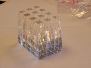
- Twelve light guides arrived from Plastic Craft on Friday April 1, 2011. They correspond to the light guides that form the inner twelve locations on a single wedge.
Dimensions / comments
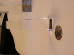
- Dimensions of Light Guides
- Histogram of dimensions relative to nominal
- Note that dimensions of the widths have some additional uncertainty since they are being measured on an angled surface.
- Both light guides #11 seem to have a discoloration (tan/brown) compared to the other ones (can be noted in the enlarged picture of the arrangement above).
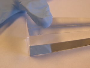
- One of the light guides #12 has a small chip near the base
Quick transmission measurement
- We took a quick look at the transmission through the light guide using the procedure shown in the Test Setup Figure with the help of Sasha and Vitaly Baturin. Used a #20 light guide. Dimensions are approximate as the setup was jury-rigged for the occasion.
- Pinhole test: Check bulk attenuation. Used two 1mm2 pinholes separated by the height of the light guide (8 cm). Measured currents were 3.2 nW/cm2 (no light guide) and 3.4 nW/cm2 (with light guide), indicating that there was no visible bulk attenuation through the light guide over the 8 cm. Note that the small aperture reduced the light to extremely low levels; background levels were on the order of about 0.3 nW/cm2.
- Transmission test: Limited entrance angles to the light guide to less than 17 degrees(side) and 23 deg (corner) using a 1x1mm2 and 12x12m2 square apertures separated by 2 cm. This corresponds to a maximum angle in the light guide of 15 degrees (maximum angle inside the fibers is 27 degrees). The light exiting the collimation system was determined by placing the light sensor directly over the 12x12 cm aperture (18.5 nW/cm2). The light through the light guide was determined by placing the light guide base over the 12x12 aperture and taking a reading of light at the top exit (10 nW/cm2), giving a transmission of about 54%. Within the accuracies of the measurements, we confirm the expectation for transmission.


