Difference between revisions of "Kuraray Fibre Tests"
From GlueXWiki
m (→To do:) |
(→Detector Setup) |
||
| Line 5: | Line 5: | ||
#The fibre is placed in a 4m x 1mm groove in a black poly-ethylene bar ("puck plastic") | #The fibre is placed in a 4m x 1mm groove in a black poly-ethylene bar ("puck plastic") | ||
#The unpainted end is inserted into and held in place by a [http://www.oceanoptics.com/products/fiberkits.asp#adapter bare-fibre SMA-connector] from Ocean Optics. | #The unpainted end is inserted into and held in place by a [http://www.oceanoptics.com/products/fiberkits.asp#adapter bare-fibre SMA-connector] from Ocean Optics. | ||
| − | #A UV LED (380nm) is used to illuminate the fibre from above | + | #A UV LED (380nm) is used to illuminate the fibre from above, and perpendicularly to the fiber's long axis |
#The spectra are obtained using an [http://www.oceanoptics.com/products/usb4000.asp Ocean Optics photo-spectrometer] | #The spectra are obtained using an [http://www.oceanoptics.com/products/usb4000.asp Ocean Optics photo-spectrometer] | ||
| − | |||
| − | |||
== Fibre Spectra == | == Fibre Spectra == | ||
Revision as of 23:17, 18 March 2009
Contents
Detector Setup
- The fibre is cut and polished on both ends with the Fiber Fin polisher (the label must be removed due to it's placement too close to the end)
- The far end of the fibre is painted black with an enamel paint (used for painting scale models).
- The fibre is placed in a 4m x 1mm groove in a black poly-ethylene bar ("puck plastic")
- The unpainted end is inserted into and held in place by a bare-fibre SMA-connector from Ocean Optics.
- A UV LED (380nm) is used to illuminate the fibre from above, and perpendicularly to the fiber's long axis
- The spectra are obtained using an Ocean Optics photo-spectrometer
Fibre Spectra
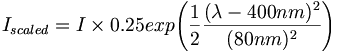
Typical fibre spectra at 10,100 and 300 cm.The green data points are the raw spectra as seen by the photo-spectrometer. The light blue points are scaled by an approximation to the quantum efficiency of a Bi-Alkali photocathode.


Bi-Alkali Quantum efficiency approximation

Attenuation lengths
- The attenuation length is found by taking the integral of the fit function of the scaled spectra and fitting that as a function of distance from the spectrometer. The fit function is a single exponential: I = A * exp(-x/B). The attenuation length is then effectively that of the fibre as seen by a PMT.
So far 6 fibers have had their attenuation lengths measured:
Attenuation length:
| fibre # |  |

|
|---|---|---|
| 01-3 | 440 | 12 |
| 23-2 | 443 | 10 |
| 26-2 | 478 | 10 |
| 32-2 | 414 | 30 |
| 33-2 | 398 | 15 |
| 49-3 | 441 | 12 |
| Avg | 436 | 15 |

The Specifications for the Scintillating Fibres required that "The bulk attenuation length of a bare fiber shall exceed 350cm, while the effective attenutaion length of the fiber shall exceed 300cm measured with a bialkali photomultiplier tube. The RMS variation in attenuation length shall be less than 10% throughout the fiber lots."
This seems to be the case.
To do:
- Make a few slight modifications to the measuring apparatus (i.e larger diffuse UV beam)
- The goal is to measure 25 fibres in the next few days
- There's always something...