Kuraray Fibre Tests
From GlueXWiki
Detector Setup
- The fibre is cut and polished on both ends with the Fiber Fin polisher (the label must be removed due to it's placement too close to the end)
- The far end of the fibre is painted black with an enamel paint (used for painting scale models).
- The fibre is placed in a 4m long groove in a black poly-ethylene bar ("puck plastic")
- The unpainted end is inserted into and held in place by a [ http://www.oceanoptics.com/products/fiberkits.asp#adapter bare-fibre SMA-connector] from Ocean Optics.
- A UV LED (380nm) is used to illuminate the fibre from above
- The spectra are obtained using an Ocean Optics photo-spectrometer
Fibre Spectra
Typical fibre spectra at 10,100 and 300 cm.The green data points are the raw spectra as seen by the photo-spectrometer. The light blue points are scaled by an approximation to the quantum efficiency of a Bi-Alkali photocathode.


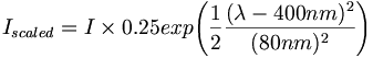
Bi-Alkili Quantum efficiency approximation