Difference between revisions of "Noise studies"
| Line 1: | Line 1: | ||
| − | After attaching the thermocouples to the small CDC prototype we observed that the post-shaper pedestal width was largest in the straws nearest the top of the prototype - it showed a steady increase moving up the detector whereas previously the widths had all been similar. At this point it went from approx 11ch (lowest row of straws) to 18 ch (highest row) (run 30765, 13 June 2010). The thermocouple wires were attached to the gas plenums at the top. After moving the thermocouple wires around and observing the signals on the oscilloscope we realised that the thermocouple wires were picking up e-m noise and passing this on to the nearest straws. | + | After attaching the thermocouples to the small CDC prototype we observed that the post-shaper pedestal width was largest in the straws nearest the top of the prototype - it showed a steady increase moving up the detector whereas previously the widths had all been similar. At this point it went from approx 11ch (lowest row of straws) to 18 ch (highest row) (run 30765, 13 June 2010, ADC range ~ 550mV). The thermocouple wires were attached to the gas plenums at the top. After moving the thermocouple wires around and observing the signals on the oscilloscope we realised that the thermocouple wires were picking up e-m noise and passing this on to the nearest straws. |
<br> | <br> | ||
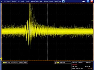
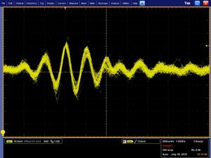
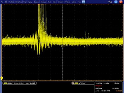
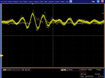
| − | scope traces for | + | scope traces for straw 16, which shows the largest amount of 4MHz pickup. The left hand side plots also show some cosmics. |
{| border="1" cellpadding="2" | {| border="1" cellpadding="2" | ||
| Line 11: | Line 11: | ||
This pickup was hardly noticeable in the lowest row of straws (xx cm below the top row). By moving another thermocouple wire around above the prototype we found that it had to be xxx cm away from the top row of straws for the extra pickup from the thermocouple to be unnoticeable. | This pickup was hardly noticeable in the lowest row of straws (xx cm below the top row). By moving another thermocouple wire around above the prototype we found that it had to be xxx cm away from the top row of straws for the extra pickup from the thermocouple to be unnoticeable. | ||
<br> | <br> | ||
| − | As well as picking up ambient e-m noise (mostly 4-5Mhz) the thermocouple control unit also contributed some noise of its own (20Mhz). When taking Fe55 data the ADCs are triggered on signals in | + | As well as picking up ambient e-m noise (mostly 4-5Mhz) the thermocouple control unit also contributed some noise of its own (20Mhz). When taking Fe55 data the ADCs are triggered on signals in straw 15 and this internal threshold was increased from xxx to xxx in order to eliminate the noise-only events. |
<br> | <br> | ||
| − | We moved the detector into a small mesh box to act as a Faraday cage. | + | We moved the detector into a small mesh box to act as a Faraday cage which decreased the pedestal sigma to 9-11 channels, for all straws. |
<br> | <br> | ||
Some oscillation in the post-shaper signal originates from the Vern-Kiebler HV supply. | Some oscillation in the post-shaper signal originates from the Vern-Kiebler HV supply. | ||
[[http://www-esd.fnal.gov/esd/catalog/main/fermilab/es7125-spec.htm]] | [[http://www-esd.fnal.gov/esd/catalog/main/fermilab/es7125-spec.htm]] | ||
| + | This is also visible in the low-voltage test output from the front of the unit as a 27kHz square wave +/- few mV. | ||
| + | {| border="1" cellpadding="2" | ||
| + | |width="300pt"|[[Image:ch16_2kV.jpg|thumb|none|300px|HV ON, Noise, 2000V, 90/10 premix, 20mV/div, 20μs/div]] | ||
| + | |width="300pt"|[[Image:ch16_0kV.jpg|thumb|none|300px|HV OFF, Noise, 0V, 90/10 premix, 20mV/div, 20μs/div]] | ||
| + | |} | ||
| + | <br> | ||
| + | We switched to a Bertan 215 HV supply which cut the pedestal sigma down to 5 to 7 channels... but also decreased the tracking efficiency by 50%. | ||
| + | So we returned to the Vern_Kiebler unit. | ||
| + | <br> | ||
| + | LV supply is HP6216, the + and - leads go to the preamp; the ground was not used. | ||
| + | <br> | ||
| + | Pickup was reduced slightly when we moved the LV supply unit inside the cage (its output wires were unshielded) but the trailing cables were undesirable and so we returned it to the DAQ rack and added shielding braid outside the cables. This braid was grounded to the LV ground, but making this connection made no observable difference to the pickup. Moving the LV back to the rack added 1mV to the pickup. | ||
| + | |||
| + | <hr><hr> | ||
| + | old scope traces below | ||
| + | <hr> | ||
HV on (HV ground & cable shielding connected) | HV on (HV ground & cable shielding connected) | ||
The envelope oscillates at about 27kHz. | The envelope oscillates at about 27kHz. | ||
| Line 32: | Line 48: | ||
|width="400pt"|[[Image:ch16_0kV_4MHz.jpg|thumb|none|400px|Noise - zoom on 4MHz, 0V, 90/10 premix, 20mV/div, 2μs/div]] | |width="400pt"|[[Image:ch16_0kV_4MHz.jpg|thumb|none|400px|Noise - zoom on 4MHz, 0V, 90/10 premix, 20mV/div, 2μs/div]] | ||
|} | |} | ||
| − | |||
| − | |||
| − | |||
| − | |||
| − | |||
| − | |||
After connecting the HV ground to the preamp end of the cable shielding | After connecting the HV ground to the preamp end of the cable shielding | ||
{| border="1" cellpadding="2" | {| border="1" cellpadding="2" | ||
Revision as of 15:04, 13 August 2010
After attaching the thermocouples to the small CDC prototype we observed that the post-shaper pedestal width was largest in the straws nearest the top of the prototype - it showed a steady increase moving up the detector whereas previously the widths had all been similar. At this point it went from approx 11ch (lowest row of straws) to 18 ch (highest row) (run 30765, 13 June 2010, ADC range ~ 550mV). The thermocouple wires were attached to the gas plenums at the top. After moving the thermocouple wires around and observing the signals on the oscilloscope we realised that the thermocouple wires were picking up e-m noise and passing this on to the nearest straws.
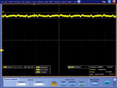
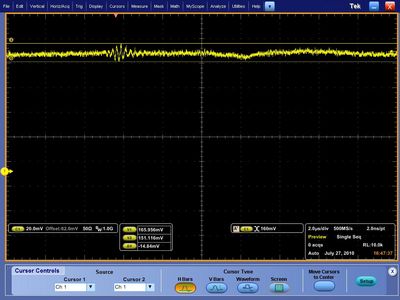
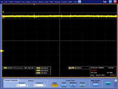
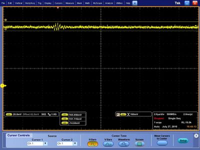
scope traces for straw 16, which shows the largest amount of 4MHz pickup. The left hand side plots also show some cosmics.
This pickup was hardly noticeable in the lowest row of straws (xx cm below the top row). By moving another thermocouple wire around above the prototype we found that it had to be xxx cm away from the top row of straws for the extra pickup from the thermocouple to be unnoticeable.
As well as picking up ambient e-m noise (mostly 4-5Mhz) the thermocouple control unit also contributed some noise of its own (20Mhz). When taking Fe55 data the ADCs are triggered on signals in straw 15 and this internal threshold was increased from xxx to xxx in order to eliminate the noise-only events.
We moved the detector into a small mesh box to act as a Faraday cage which decreased the pedestal sigma to 9-11 channels, for all straws.
Some oscillation in the post-shaper signal originates from the Vern-Kiebler HV supply. [[1]] This is also visible in the low-voltage test output from the front of the unit as a 27kHz square wave +/- few mV.
We switched to a Bertan 215 HV supply which cut the pedestal sigma down to 5 to 7 channels... but also decreased the tracking efficiency by 50%.
So we returned to the Vern_Kiebler unit.
LV supply is HP6216, the + and - leads go to the preamp; the ground was not used.
Pickup was reduced slightly when we moved the LV supply unit inside the cage (its output wires were unshielded) but the trailing cables were undesirable and so we returned it to the DAQ rack and added shielding braid outside the cables. This braid was grounded to the LV ground, but making this connection made no observable difference to the pickup. Moving the LV back to the rack added 1mV to the pickup.
old scope traces below
HV on (HV ground & cable shielding connected) The envelope oscillates at about 27kHz.
HV off (HV ground & cable shielding connected)
After connecting the HV ground to the preamp end of the cable shielding
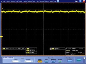
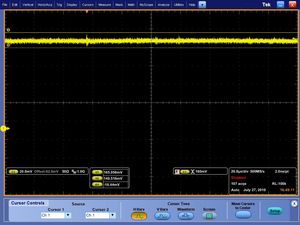
The traces below also show ch16 at a much smaller timescale, 20 μs/div, with the HV supply to the CDC prototype on and off.
