SiPM Radiation Hardness Test
From GlueXWiki
SiPM Radiation Hardness Test in Hall A
Contents
Test Plan
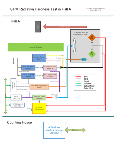
System Diagram
Device List
- Control Computer: transversity.jlab.org: (129.57.164.28)
- GPIB over IP: GPIB-ENET/100: agpib.jlab.org (129.57.192.73)
- Serial Port Server: ESP904: portservha50.jlab.org (129.57.192.78)
- USB over IP: AnywhereUSB/5: ausb.jlab.org (129.57.192.75)
- Oscilliscope: TDS3034: dosci.jlab.org (129.57.192.77)
- Power Outlet: APC Outlet Control: hlauser:hlauser@hareboot12.jlab.org (129.57.192.76)
- Outlet 1: Pulse Generator
- Outlet 2: Temperature Box
- Outlet 3: Oscilliscope
- Outlet 4: GPIB over IP
- Outlet 5: Power Supply for Hamamatsu Unit
- Outlet 6: Power Supply for SensL Unit
- Outlet 7: Picoamp Meter
- Outlet 8: Serial Port Server
- USB to Serial HUB: ComHUB
- Serial 1 (COM5): Power Supply for Hamamatsu Unit
- Serial 2 (COM6): Power Supply for SensL Unit
- Serial 3 (COM7): Oscilliscope
- Serial 4 (COM8): Temperature Box
- Picoamp Meter x2: Keithley-485 (GPIB)
- GPIB Address: 1 (Hamamatsu); 2 (SensL)
- Pulse Generator: HP-8116A (GPIB)
- GPIB Address: 4
- Power Supply x2: B&K-1787B (RS232)
- Temperature Meter: CN77544 (RS232)
Power Connection and Settings
- Power Cable Color Code
- Black: Ground
- Yellow: -5.0 V
- Red: +2.1 V
- Blue: Hamamatsu Bias Voltage
- Green: SensL Bias Voltage
- SiPM Bias Voltage Correction vs Temperature
- Hamamatsu: 56 mV/C (70.27 at 20 C)
- SensL: 23 mV/C (28.6 at 20 C)
Event Log
2010 Mar 17
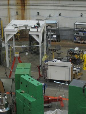
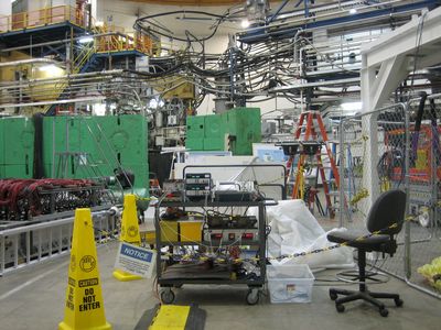
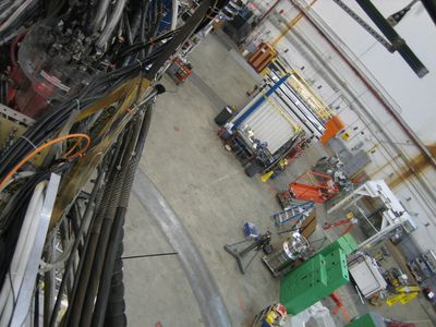
- Photos of SiPM test setup.
- All Hardware intrustruments have been connected.
- The SiPM box is put on top of the cryo target parking support which is at about 135 degrees to the left side of the beam and 20 meters away from the target.
- The real time neutron counter is put right next to the SiPM.
2010 Mar 18
- Have all the remote communication working properly.
- Other than the oscilloscope, Labview programs to all the rest devices are ready.
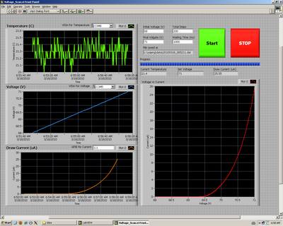
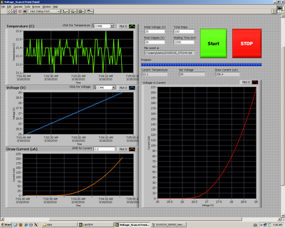
- Did first measurement of the correlation between the draw current and the bias voltage.
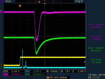
- Signals on Oscilloscope with 70.5V on Hamamatsu and 28.5V on SensL are shown as well.
2010 Mar 19
- Finished Oscilloscope initialization program, the readback program is done as well but not quite stable
- Increase the pulse frequency to 1.0 kHz, here is the final configuration for the pulse generator
* Direct DC couple to the LED
* Frequency: 1.0 kHz
* Width: 8.0 ns
* High Level: 5.0 V
* Low Level: 0.0 V
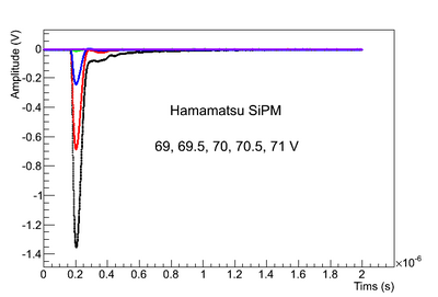
- Tested the draw current corresponding to the voltage level and recorded the oscilloscope signals (average of 128 waveforms)
- Removed both SiPMs from the box for Hall closing.
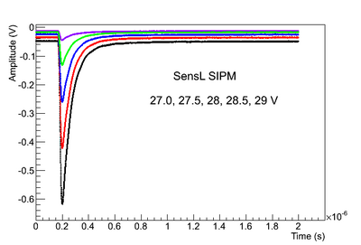
- SiPM signal shape vs Voltage
2010 Mar 21
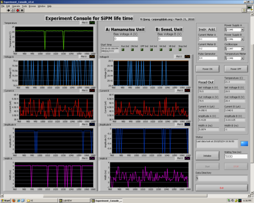
- Finished first version of the Central Control VI, change all serial communication timeout to be 1 second
- Stress test
2010 Mar 22
- Stress test failed, system won't run VI after rebooting. Maybe it's time to rebuilt the XP system on the computer
2010 Mar 23
- Brought transversity.jlab.org to CC for a system rebuilt
- At the mean time, upgraded the Central Control VI to version 2 with a more responsive interface and better timing control.
2010 Mar 24
- CC rebuilt the XP System
- Installed all necessary software, all devices are up and running well
- Changed GPIB timeout to be 1 second, should not have any timeout problem
- Stress test with Central Control VI without writing file to the disk
Data Analysis
Data History
- 20100318 Pulse Frequency: 500 Hz
- 20100319 Pulse Frequency: 1.0 kHz
