SiPM Radiation Hardness Test
Contents
- 1 Introduction
- 2 Probing Neutron and Its Damage to Silicon Detectors
- 3 Irradiation in Hall A
- 4 Irradiation with RadCon AmBe Source
- 5 Fluence simulation of Hall D
- 6 Temperature Test with RadCon AmBe Source
- 7 SiPM in Tagger Hall
- 8 Summary of Radiation Damage to Hamamatsu SiPMs
- 9 After Pulse
Introduction
The of goal of the SiPM Radiation Hardness tests is to reasonably predict the life time of such a detector in normal Hall D GlueX production running as the readout of BCal. Since most of the damage to SiPM is expected coming from neutron, the study is focused on the neutron damage only. A series of tests have been performed with both electron beam on Pb target at Hall A and RadCon AmBe neutron source.
Probing Neutron and Its Damage to Silicon Detectors
Neutron probe
The neutron flux in both Hall A and RadCon neutron source is measured by portable neutron survey meter (BF3) [1]. What this probe measures is equivalent dose [2] in the unit of rem, which is a measure of the radiation dose to tissue where an attempt has been made to allow for the different relative biological effects of different types of ionizing radiation.
The conversion coefficients are plotted here according to ICRP 74 [3]

Damage to silicon detector
Numerous observations have led to the result that damage effects by energetic particles in the bulk of any material can be described as being proportional to the so called displacement damage cross section. This quantity is equivalent to the Non Ionizing Energy Loss (NIEL) and hence the proportionality between the NIEL-value and the resulting damage effects is referred to as the NIEL-scaling hypothesis. The NIEL-value can also be referred to as the displacement-KERMA, i.e. the Kinetic Energy Released to MAtter (in this case silicon)
As recommended for the LHC silicon detector study, the equivalent neutron radiation damage to silicon detector normalized to 1 MeV neutron is plotted here [4].

Conversion from rem to 1MeV neutron fluence
With the previous two kinds of conversion factors and neutron energy spectrum, one can convert the measured neutron flux to 1 MeV neutron fluence.
Irradiation in Hall A
Test setup
- The test was performed in Hall A during P-Rex experiment [5]
- Electron beam energy: 1 GeV
- Target: 0.5 mm Pb
- Location of SiPM: 135 degrees backward, 20 meters away from target
- More details can be found in Test Plan and Setup in Hall A
Simulation
Dr. Pavel Degtiarenko did a simulation using GEANT3 for the neutron background in Hall A. The result of neutron energy spectrum is shown [6]

Conversion factor for Hall A
- Dose to fluence: 1 rem → 2.4 × 10⁷ neq/cm2
Rate estimation
- Estimated dose rate: 3.1 rem/H
- The dose rate estimation with 0.5 mm Pb target and 50 μA is 7.64 rem/H.
- In reality, the Pb target thickness was gradually reduced due to the beam damage, the effective thickness of the target during the SiPM irradiation was found to be 40% using the relative change of the neutron neutron dose rate measured by the neutron probe:
- 03/28/2010 11:00: 950 mrem/H@22.8 μA → 2.12 rem/H@50 μA (Pb#3 first time in beam)
- 04/06/2010 07:00: 1.53 rem/H@44.2 μA → 1.73 rem/H@50 μA (Pb#3 last time w/o collimator)
- 04/16/2010 02:00: 0.99 rem/H@18.0 μA → 2.75 rem/H@50 μA (Pb#3 first time w/ collimator)
- 04/20/2010 22:00: 1.41 rem/H@49.7 μA → 1.42 rem/H@50 μA (Start of SiPM test)
- 04/22/2010 09:00: 1.30 rem/H@49.5 μA → 1.31 rem/H@50 μA (End of SiPM test)
- Measured dose rate: 4.7 rem/H
- 1.3 rem/H from raw reading.
- The neutron probe underestimates the actual Hall A dose rate by a factor 3.6 due to lack of sensitivity to high energy neutrons (>20 MeV). Such a factor was calculated by comparing to the damage results with AmBe source (calibration of neutron probe).
- Very good agreement to the simulation.
- 1 MeV equivalent neutron fluence (simulation): 21000 neq/s/cm2
3×3 mm2 SiPM test in Hall A
- Time of irradiation: 04/20/2010 21:00 - 04/22/2010 07:00
- Final dose: 153 rem (measured & corrected)
- Temperature: 21.3°C
- Initial dark current: 8.2 μA for Hamamatsu and 125 μA for SensL
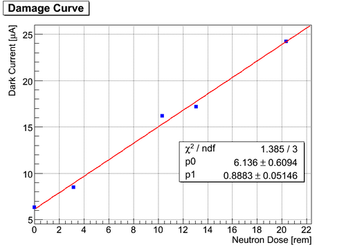
Immediate damage results
- Dark current linearly increases as a function of 1MeV neutron fluence.
- Whether or not power the SiPM will not change the damage effect (the power was turned off on purpose during the big blank period).

- Compmared to the change of dark current, the changes of the signal shape (gain and the width) are very small. The colors represent the neutron dose: red (initial) -> violet (final)


- The VI responses of both SiPMs were not effected by the radiation: no change of break down voltages.


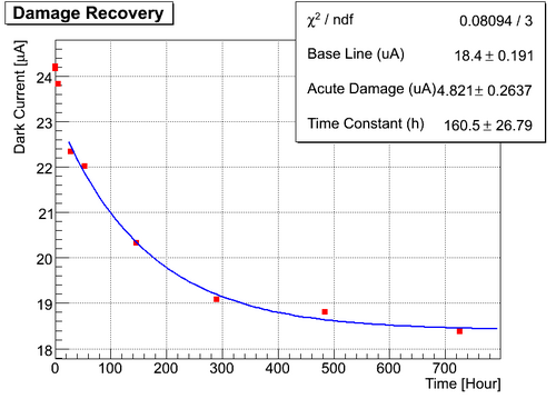
Recovery from radiation damage
- The dark current from both SiPM samples recovered by about 50% with time constant of 10 days.
- The gain was fully recovered.
- Taking the bias voltage adjustment into account, the dark current has an exponential relation to the ambient temperature:
- I(dark) ~ exp(a*(T-T0))
- a for Hamamatsu: 0.061±0.003/C
- a for SensL: 0.047±0.002/C


Other info
- Report to GlueX meeting (2010/05/10): link to docDB
- Dark rate measurement shows a increase of noise level consistent with the increase of dark current:Carl's report
- Idark ~ σpedestal2
1×1 mm2 SiPM test in Hall A
- Temperature: ~ 21.3 degree C
- SiPM Serial Number: 1260
- Irradiation time: 06/11/2010 11:20 - 06/15/2010 10:00
- Total dose: 123 Rem (34.3 rem x 3.6)
Test Result
- ADC dark spectrum before/after irradiation and two months later


- Formula used in the fit:
-
- Note: the pre-amplifier used in the first two tests (before and post) was from Stepan with a total gain of 105 while during the last test (anneal) the pre-amplifier from Fernando was used with a gain of 65.
- Immediate increase of dark rate: factor of 37
- Permanent increase of dark current: factor of 18: Carl's measurement
- Permanent increase of dark rate: factor of 21
- Cross-talk: 15%

Irradiation with RadCon AmBe Source
Conversion factor for AmBe neutron source
- The AmBe source has an narrow neutron energy spectrum averaged at 4 MeV [7] page82

- Dose to fluence: 1 rem → 3.3×10⁷neq/cm2
Test Condition
- The AmBe source in RadCon has the following dose rate:
dose rate = [13/D2]*[1+(0.248*D)2.2375*e-0.3536*D] mrem/H
where D is the distance from the source in the unit of meter
- One 1×1 mm2 and one 3×3 mm2 SiPMs from Hamamatsu together with their pre-amplifiers were irradiated by this source
- The distance is 17 cm and dose rate is 0.45 rem/H
- Irradiation time: 07/12/2010 14:40 - 07/15/2010 14:25
- Total dose: 32±2 rem
Results
1x1 mm SiPM
- ADC spectra before/after irradiation and 1 month later:


- Immediate increase of dark current: factor of 6.4 Carl's Measurement
- Permanent increase of dark current: factor of 4
- Permanent increase of dark rate: factor of 3.5
- Cross talk: 13%
3x3 mm SiPM
- ADC spectra before/after irradiation and 1 month later:


- Immediate increase of dark current: factor of 7.1 Carl's Measurement
- Permanent increase of dark current: factor of 4.7
- Permanent increase of dark rate: factor of 4.1
- Cross talk: 14%
Calibration of neutron probe for Hall A measurement
- Use the increase of dark current as a bench mark
- WIth AmBe source, it took 32 rem to permanently increase the Hamamatsu SiPM dark current by a factor of 4.4.
- 32 rem → 1.06×10⁹ neq/cm2
- In Hall A, with Pb target, it took 12 rem (measured, NOT corrected, 9.2 hours with 1.3 rem/H dose rate) to permanently increase the Hamamatsu SiPM dark current by a factor of 4.4.
- 12 rem → 2.9×10⁸ neq/cm2
- The correction factor should be: 1.06×10⁹/2.9×108 = 3.6
- WIth AmBe source, it took 32 rem to permanently increase the Hamamatsu SiPM dark current by a factor of 4.4.
Fluence simulation of Hall D
Pavel recently updated his simulation for the neutron flux through SiPMs with normal Hall D production condition.
Simulation Condition and Results
- Detector location: Z = 462 cm
- Rate of photon beam before collimator: 11 GHz
- Dose rates and energy spectra with Hydrogen target
- Flux in downstream SiPM area with Hydrogen target
- Flux in upstream SiPM area with Hydrogen target
- Dose rates and energy spectra with Helium target
- Flux in SiPM area with Helium target
- Flux in upstream SiPM area with Helium target
Hydrogen Target
Downstream Detector
- The energy spectrum of neutron from Hydrogen target:

- Dose to fluence: 1 rem → 2.6×10⁷ neq/cm2
- At 65-90 cm
- Dose rate: 4.3-3.3 mrem/H
- Total neutron flux: 90-76 Hz/cm2 (54-43 forward, 37-33 backward)
- Neutron flux > 10 MeV: 4.3-2.6 Hz/cm2 (3.1-1.7 forward, 1.2-1.0 backward)
- 1 MeV equivalent neutron fluence: 31-23 neq/s/cm2
Upstream Detector
- The energy spectrum of neutron from Hydrogen target:

- Dose to fluence: 1 rem → 2.7×10⁷ neq/cm2
- At 65-90 cm
- Dose rate: 1.0-0.4 mrem/H
- Total neutron flux: 20-16 Hz/cm2 (3.5-3.2 forward, 17-13 backward)
- Neutron flux > 10 MeV: 0.7-0.4 Hz/cm2 (0.1-0.0 forward, 0.6-0.4 backward)
- 1 MeV equivalent neutron fluence: 8-3 neq/s/cm2
Helium Target
Downstream
- The energy spectrum of neutron from Helium target:

- Dose to fluence: 1 rem → 2.6×10⁷ neq/cm2
- At 65-90 cm
- Dose rate: 6.5-4.9 mrem/H
- Total neutron flux: 140-108 Hz/cm2 (94-67 forward, 46-41 backward)
- Neutron flux > 10 MeV: 7.0-4.0 Hz/cm2 (5.6-3.0 forward, 1.3-1.1 backward)
- 1 MeV equivalent neutron fluence: 47-35 neq/s/cm2
Upstream
- The energy spectrum of neutron from Helium target:

- Dose to fluence: 1 rem → 2.4×10⁷ neq/cm2
- At 65-90 cm
- Dose rate: 1.2-0.8 mrem/H
- Total neutron flux: 35-28 Hz/cm2 (4.0-3.8 forward, 31-24 backward)
- Neutron flux > 10 MeV: 1.5-1.1 Hz/cm2 (0.5-0.1 forward, 1.0-1.0 backward)
- 1 MeV equivalent neutron fluence: 8-6 neq/s/cm2
Life Time of SiPMs in Hall D
- Our current calorimeter design allows a factor 5 increase of the dark noise, and the 1 MeV neutron fluence needed according to Hall A simulation: 11 hours of 50 μA beam → 34 rem → 8.2×10⁸neq
- At 65-90 cm (inner-outer radius of BCal), to reach same 1 MeV neutron fluence:
- Hydrogen target: 0.9-1.1 years for downstream and 3-9 years for upstream of full-time running
- Helium target: 0.6-0.8 years for downstream and 3-4 years for upstream of full-time running
- Factors to increase life time of SiPM
- Running efficiency: 33%
- Lower temperature: 20°C→5°C will reduce the dark rate by a factor of 3 (has been very verified with non-irradiated samples).
- Expected life time with high luminosity production (108 γ):
- 8 - 10 years for Hydrogen target
- 5 - 7 years with Helium target
Temperature Test with RadCon AmBe Source
Test Condition
- Samples Irradiated product page:
- -4°C: 1854, 1855, 1856, 1857, 1858, 1859
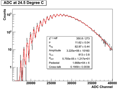
- room temperature (24.5°C): 1853, 1860, 1861, 1862, 1863, 1864, 1264(previously irradiated with AmBe)
- Recovery Temperature:
- -4°C: 1854, 1856, 1861, 1862
- 25°C: 1858, 1859, 1853, 1860, 1264
- 60°C: 1855, 1857, 1863, 1864
- Irradiation Period:
- 2010/09/16 14:50 - 2010/09/20 14:50
- Total dose: 43.2 rem
- Recovery Period:
- -4°C: since 2010/09/20 23:50
- 25°C: since 2010/09/20 14:50
- 60°C: since 2010/09/21 12:20
- 60°C for sample 1854, 1861 (previously -4°C group) and 1858, 1860 (previously 25°C group)
- More need to be added:
- Second Irradiation Period:
- 2011/01/14 14:40 - 2011/01/18 14:45
- Total dose: 52 rem
- -4°C: 1854,1855,1856,1857,1858,1859
- Room temperature: 1264,1853,1860,1861,1862,1863,1864
- Recovery:
- all at 50°C
SiPM in Tagger Hall
SiPM Info
- Photonique 2x2 mm SiPM
- Rated Bias Voltage: 37V
AmBe Irradiation Test
- Time: Aug 30, 2010 - Sep 1, 2010
- Temperature: 23°C
- Bias Voltage: 36.3V
- Total Dose: 20 rem
- Dose Rate: 0.45 rem/H
-

Recovery Test
- Time: since 10:00 AM, Sep 1, 2010
- Temperature: 24.2°C
- Bias Voltage: 36.3V
-

V-I Curve at Different Stages

Summary of Radiation Damage to Hamamatsu SiPMs
Previous 1×1 mm and 3×3 mm Samples Irradiated by AmBe Source
- Radiation Dose: 32 rem → 1.1×10⁹neq/cm2
- Temperature: 24.5°C
- Dark Current/Rate: increased by a factor of 4.1
- Dose to increase dark current/rate by a factor of 5:
- 41 rem → 1.4×10⁹neq/cm2
Summary of 1×1 mm Samples Irradiated by AmBe Source
- Radiation Dose: 43.2 rem → 1.43×10⁹neq/cm2
- Initial Dark Current (Gain: 7.5×10⁵, T: 25°C) : 84±2 nA
-
- Initial Dark Rate : 563±20 kHz
-
- Prompt Radiation Damage:
- -3°C group: 87±4 nA → 771±66 nA (8.9× ±9%)
-
- 24.5°C group: 86±2 nA → 660±38 nA (7.7× ±6%)
-
- -3°C group: 87±4 nA → 771±66 nA (8.9× ±9%)
- Damage Recovery:
-
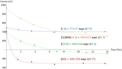
- 60°C group: 87 nA → 708 nA(8.1×) → 349 nA(4.0×); Recovery Time Constant: 0.77 day; Recovered Fraction: 62%
- 24.5°C group (preliminary): 85 nA → 693 nA(8.2×) → 449 nA(5.3×); Recovery Time Constant: 4.1 days; Recovered Fraction: 46%
- -4°C group: not enough data
- Irradiated sample@24.5°C (preliminary): 311 nA(3.7×) → 971 nA(12×) → 646 nA(7.7×); Recovery Time Constant: 4.3 days
-


Conlusions and Tasks
- Recovery time is strongly temperature dependent.
- Fraction of recovery to total damage may also be temperature dependent, to check it:
- Take more data with 24.5°C and -4°C groups,
- Cool 60°C group to room temperature or -4°C to check changes: equilibrium of damage clusters at different temperature?
- Re-irradiated 60°C group samples and anneal at 40°C
- Radiation damage and recovery will not change the upcoming damage rate:
- Increase of dark rate/current vs dose is constant,
- The fomulism of simultaneous recovery during damage will work.
- Dose to increase dark current/rate by a factor of 5:
- Assuming no recovery: 23 rem → 0.76×10⁹neq/cm2
- Assuming 60°C result: 58 rem → 1.9×10⁹neq/cm2,
- Assuming preliminary 24.5°C result: 40 rem → 1.3×10⁹neq/cm2,
- 24.5°C result is more consistent with previous estimation.
Temperature Dependence
- Change of Cooling Effects on Dark Current and Dark Rate
- Sample 1254 and 1255 were irradiated at -3 °C, and sample 1253 was irradiated at 24.5 °C
- The radiation slightly changed the temperature dependence of dark rate/current:
-
- To decrease dark rate by a factor of 3 after irradiation:
- Drop temperature by 17°C.
- Further measurements are needed for temperature dependence of baseline damage and recovery time.


Irradiation Test in Hall A
Tests with previously irradiated samples
4×4 3×3 mm array
- Radiation Dose (Simulation: 3.1 rem/H): 101 rem → 2.4×10⁹neq/cm2
- Temperature: 21.3°C
- Dark Current: 8.2 μA → 202 μA(25×) → 94 μA(11.5×); Recovery Time Constant: 9.0 days; Recovered Fraction: 56%
- Dose from simulation to increase dark current/rate by a factor of 5:
- 34 rem → 0.82×10⁹neq/cm2
- Uniformity test of dark rate:
- Reference Sample: 4.5±0.2 MHz
-
- Irradiated Sample: 40.3±3.8 MHz
-
- Reference Sample: 4.5±0.2 MHz


1×1 mm Sample
- Increase of dark rate compared to the one irradiated with AmBe source and showed a factor of 2.6 discrepancy:
20(increase in Hall A) x 32 rem(dose with AmBe) x 3.3 (conversion for AmBe)/2.8(increase with AmBe)/123 rem(dose in Hall A)/2.4(conversion for Hall A) = 2.6
Life Time in Hall D
- Hydrogen target with 108 γ/s (from Pavel's GEANT simulation): 3.8 mrem/H → 0.99×10⁵ neq/H/cm2
- Days to increase dark current by a factor of 5 (NO operation efficiency considered):
- Based on AmBe irradiation result:
- Without recovery: 0.76×10⁹ neq/cm2 → 320 days,
- With recovery: 1.3 - 1.9×10⁹ neq/cm2 → 550 - 800 days.
- Based on Hall A simulation:
- With recovery: 0.82 ×10⁹ neq/cm2 → 345 days.
- Based on AmBe irradiation result:
- Decrease the running temperature by 17°C will reduce dark rate by a factor of 3.
- Normal experimental operation efficiency: 33%
After Pulse
Study by Simply Fitting the Tail
- Upper limit of after pulse: after pulse + pulse shape + light input profile
- Fit of after pulse
- Signal range: 60 - 120 ns
-


- Dependence of after pulse
-

- Temperature dependence of signal output
-

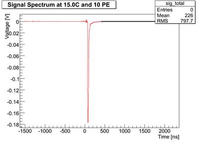
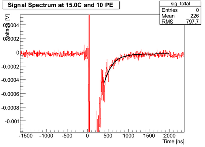
Study with Very Small Signal Input
- To remove pulse shape effect
- Condition
- Average photon input ~ 1 PE
- Signal range: 60 - 120 ns and peak at 80 ns
- Temperature: -7°C
- Cuts to select events with only 1 PE in signal window and nowhere else
-

- Residue
- Average of all events is normalized to single photon amplitude by comparing leading edges
-
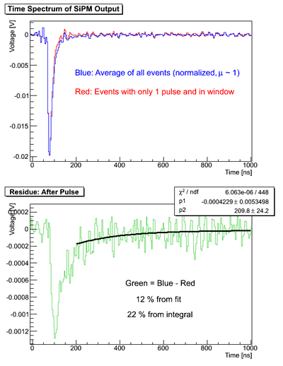
- The fitting of the tail of the residue gives consistent result of previous study: 12%
- But more residue found in the signal range: +10%, cross talk with shorter delay compared to after pulse?

Study by ADC Fitting
- Fit of ADC in signal range: 60 - 120 ns
-
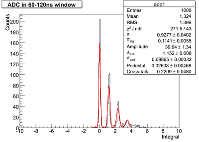
- Assuming all effect from cross-talk (fast component): 22%
-
- Fit of ADC after signal starts: 60 - 2060 ns
-
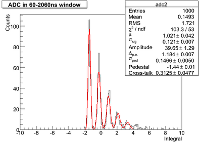
- Cross-talk (fast) + After pulse (slow) = 31%
- After pulse = 31% - 22% = 9%, consistent with tail fitting
- Cross-talk Seems not very consistent with previous study without signal input (~ 15% with 200 ns window), probably due to the uncertainty of pulse timing in the random case
- Compared to an early SiPM ADC fit with light input of 20 PE
-
-


