Solenoid Operations
Contents
The Solenoid Magnet
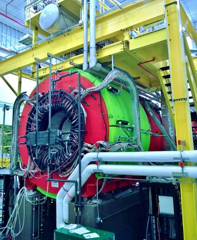
The principle analysis magnet for the GlueX spectrometer is a superconducting solenoid made from the Large Aperture Solenoid Spectrometer (LASS) solenoid built at Stanford Linear Accelerator Center (SLAC) in 1971. The LASS solenoid consists of four separate coils located in separated vacuum vessels. Three coils were later used a second time for the Muon decays into Electron and GAmma ray (MEGA) experiment at Los Alamos National Lab from 1993 through 1995. During the MEGA experiment, the coils had electrical shorts and leaks to the insulating vacuum along with deteiorated superinsulation and instrumentation. In order to use them for the GlueX experiment, all four LASS coils have been extensively repaired, refurbished and tested at Jefferson Lab. The four coils were then assembled in Hall-D. The final GlueX solenoid has a bore of 1.85~m and measures 4 m long.
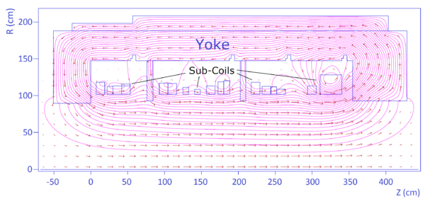
The magnet consists of 4608 windings(turns) of conductor in total. The windings are grouped into 19 sub-coils and distributed in four coils. The conductor is made of two copper bars 7.62 mm wide and about 2 mm thick, with a band of about 1~mm thick NbTi superconductor composite soldered in between them. These double-pancake windings are not insulated at their sides and are separated by a 0.64 mm thick stainless steel band co-wound with the cable, and insulated from the cable on both sides by Mylar bands of 0.2 mm thick.
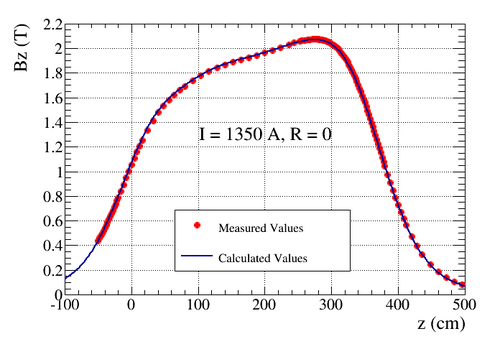
When powered with the maximum current of 1350 A, the solenoid generates a field close to 2 Tesla in the bore. The full inductance of the solenoid is about 26 H.
Routine Operation
As the superconducting solenoid is very complex system, the operation of such system requires a lot of knowledge and experiences. The commissioning, troubleshooting, tuning of ground fault and quench detectors, Power ON and OFF, change current will be conducted by authorized experts only.
The responsibilities of the shift workers include:
- Monitor the overall status of the solenoid: current, field, interlocks, voltages, cryogenic levels etc.
- Notify experts when anomalies happen.
- Ramp the magnet per request of run coordinator.
- Make log entries to the HDLOG and HDSOLENOID logbooks.
How-To
Open Solenoid EPICS Control GUIs
The Solenoid Main GUI can be opened from the Hall-D's main EPICS GUI.
If not opened, follow these steps:
- If in counting house, go to step 3 directly. If offsite or using a person computer, log on to JLab's Login Gateway:
ssh -X yourusername@login.jlab.org - If not already in the device network, log on to the Hall Gateway (hallgw):
ssh -X yourusername@hallgw, use your two-step crytocard to generate passcodes. - Log on to one of the gluon machine gluon01 - gluon05, gluon27-gluon30, with account hdops:
ssh -X hdops@gluonX, ask Yi Qiang [1] or Hovanes Egiyan [2] for password. - Type
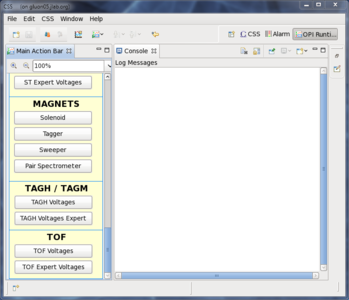
gluex_cssto bring up the CSS framework. Browse and open one of the solenoid profiles: Solenoid or Solenoidn, where n = 2 - 5. - Switch to OPI Runtime perspective if not already,
 .
. - Open Main Action Bar using short cut

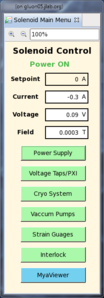
- From Main Action Bar, click the Solenoid button in section MAGNETS to bring up the Solenoid Main GUI.
Basic status of the power supply will be shown on the main menu, in order to access detailed information and functions, click the corresponding buttons.
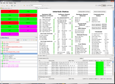
Screenshots of all GUI pages can be found in Solenoid_EPICS_Screen.
note: MobaXterm is recommended for Windows users, and a copy is available on M: drive M:\halld-online\MobaXterm.exe
Open EPICS Alarm GUI
The EPICS Alarm GUI is based on the same framework of the control GUIs. One can easily switch to the Alarm perspective to bring up the Alarm Handler of the whole Hall-D system.

The list of alarm thresholds is presented in Media:Solenoid_Alarm.pdf.
Ramp the Magnet
Special care is need to prevent sudden change of the solenoid current from damaging the magnet. And the solenoid current is ramped with stops and various ramp rates:
- 0 - 800 A: 0.2 A/s
- sit at 800 A for 15 minutes
- 800 - 1000 A: 0.12 A/s
- sit at 1000 A for 60 minutes
- 1000 - 1200 A: 0.06 A/s
- sit at 1200 A for 60 minutes
- 1200 A - beyond: 0.06 A/s
The ramp down follows the reversed procedure.
Such a stepped ramp profile is automatically executed by an EPICS State Machine through EPICS GUI. To ramp the magnet, follow the steps:
- Check the status of the Solenoid including cryo and vacuum, make sure all interlocks except for the MPS main contactor are OK.
- Open the MPS GUI by clicking Power Supply button in the main menu.
- Verify the MPS is in Remote mode. If not, click the Set Remote button.
- If the MPS is not ON, turn it ON by clicking the Turn ON MPS button.
- Type the desired current to field next to Final Goal.
- Click Ramp button to start a ramp. The button should then switch to Cancel and the status indicator will tell you that a ramp is in progress.
- Click Cancel button to abort a ramp.
For rare cases, one may want to ramp the magnet using manual settings
- Open MPS Manual Control by clicking the Manual button.
- Type in desired current and ramp rate in the fields next to Set Point.
- Click Ramp to start a ramp.
- Click Cancel to abort a ramp.
- Click Auto button to go back to Automatic Mode.
Take High Speed Data using PXI
High speed data are needed to trouble shoot issues associated with the solenoid. The PXI ROOT file recorder needs to be turn on every time the magnet is being ramped. To do so
- Open the Voltage Taps/PXI GUI from the main menu.
- Verify that the PXI status shows DAQ Running.
- Click Start Recording ROOT File button to start a writing session. One will notice a new file is generated and the file size is increasing.
- Click Stop Recording ROOT File button to stop a writing session after the solenoid is settled.
- One can check the recorded data using the Analyzer.
More information of PXI can be found in expert page.
Reboot EPICS IOCs
There are two IOCs associated with the Solenoid operation:
- Solenoid PXI Interface
- IOC to record high speed data from the PXI
- Solenoid PLC Interface
- IOC to pass tags between PLC and EPICS
One can reboot eith IOC following the procedure listed here
Every time after Solenoid PLC Interface is rebooted, one needs to reload the alarm setting from the Interlock GUI to store all the alarms.
- Open the Interlock GUI from the Main Menu.
- Click Restore Alarm Settings.
- Select
alarm_commissioning.snapfrom the file list and click Restore.
Access PLC HMI Interface
The HMI screens are for expert only. halldsc7 currently serves as the Remote Desktop Server to access these screens. Right now, only ONE connection is allow at a time, so please quit the remote desktop if not needed. You can access them by using any Linux terminals in the Counting House: gluon01a, gluon02, gluon03, gluon04 and gluon5. To do so, follow theses steps:
- Open a terminal from any of the gluon machines.
- Start remote desktop in fullscreen mode by typing
rdesktop -f halldsc7in the terminal - In the Windows Log In screen, choose Other User, use JLAB\halldusers for username, ask Yi [3] or Hovanes [4] if you do not know the password.
- Once logged in, double click the FactoryTalk Client shortcut on the desktop, choose ...\Hall_D.cli application and click run to start the HMI screens.
- Once done, please log off the remote desktop. You can leave the screens running though.
More information about HMI screens can be found in expert page.
When a Trip Happens
- Call Mechanical On-Call (757-544-7258) every time when the power supply trips!
- DO NOT clear interlock status or attempt to change MPS state before the Solenoid On-Call responses!
- Make screen shots of Solenoid status and post them to the HDLOG and HDSOLENOID logbooks: Interlock, MPS, Voltage, Cryo, Vacuum, Strain Gauge.
Only when instructed by the expert, follow the following steps to turn MPS back ON:
- Clear interlock by clicking Reset Interlocks button from the Interlock screen.
- Verify that the MPS is in
REMOTEmode from the MPS screen. If not, click Set Remote button to switch. - Clear MPS interlock by clicking Reset MPS button. Second attempt may be needed to clear all the error bits.
- Turn on the power supply by clicking Turn ON MPS button.
Expert personnel
The individuals responsible for checking that the solenoid is ready to take data and setting its operating parameters are shown in following table. Problems with normal operation of the solenoid should be referred to those individuals and any changes to their settings must be approved by them. Additional experts may be trained by the system owner and their name and date added to this table.
| Name | Extension | Cellphone | Pager | Date of qualification |
|---|---|---|---|---|
| Mechanical On-Call | 544-7258 | Nov 10, 2014 | ||
| George Biallas - Solenoid | 269-7535 | 813-1179 | [5] | June 12, 2014 |
| Beni Zihlmann - Solenoid/PXI | 269-5310 | 926-9671 | [6] | June 12, 2014 |
| Mark Stevens - Power Supply | 269-6383 | 318-1576 | [7] | June 12, 2014 |
| Scot Spiegel - MPS/Solenoid | 536-5900 | [8] | June 12, 2014 | |
| Jonathan Creel - Cryogenics | 269-5925 | 869-8910 | [9] | June 12, 2014 |
| Dave Butler - PLC | 329-2583 | 329-2583 | [10] | June 12, 2014 |
| Carroll Jones - LCW | 876-1778 | 876-1778 | [11] | Nov 14, 2014 |
