2011 Hall B FCAL Beam Test
Contents
2011 Hall B FCAL Beam Test
Test out 25 FCAL modules using Hall B electron beam.
- HBList Task list for Hall B to coordinate work in the hall with the work coordinator, Doug Tilles (unaccessible from offsite)
- HDFCALEST electronic log book (from on-site)
- HDFCALTEST electronic log book (from off-site)
Meetings
- Monday May 28
- Monday May 21
- Monday May 14
- Monday May 07
- Monday Apr 30
- Monday Apr 23
- Monday Apr 16
- Monday Apr 09
- Monday Apr 02
- Monday Mar 26
- Monday Mar 19
- Monday Mar 12
- Monday Mar 05
- Monday Feb 27
- Monday Feb 13
- Monday Jan 30
- Monday Jan 23
- Monday Dec 5
Schedule
Beam
2.2 Gev through ~March
Electron running Mid February
5.5 GeV after ~March
Construction
- Target date to finish construction - 11/02/2011 (Wed)
- Drive from IU to JLab for installation - 11/08/2011 (Tue)~
Setup
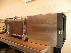
Pictures of setup to hold detector and trigger scintillators. Built by John Frye and the machine shop at IU, and shown here:
See also Matt's Flickr page
Electronics
- Have put together NIM modules at IU, no need to borrow any NIM modules
- Have tested inputs/outputs, all units working
- Output widths of all NIM modules with adjustable widths set to 50 ns. As long as the rate of electrons coming in is less than 20 MHz, we should be fine (the total rate on the CLAS tagger should be on this order).
- All thresholds on discriminators have been adjusted to 50 mV.
- List of electronics are shown here:
List of FCAL Beamtest Electronics
Software
Visit the special page on Mini-FCAL Beam Test Software
Geometry
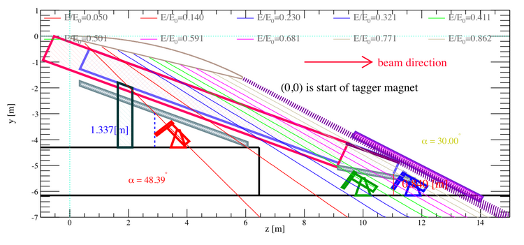
The geometry for the Hall B tagger and our detector setup is shown in
Beam Rates
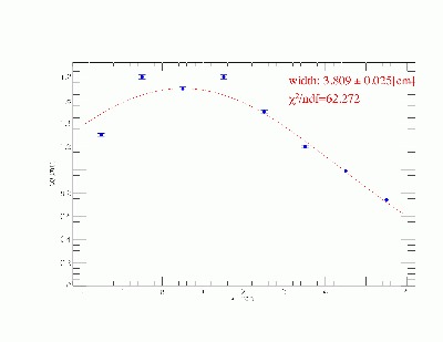
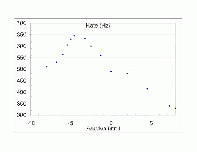
- The difference between the two figures seems to stem from the scintillating fibres having
directional dependence on the incoming electrons. Without any veto on the incoming electron direction, it seems we will be saturated with scattered electrons.
- Also note that these measurements were done near the end of the beam, where there is
lots of scattering as the main beam exits the vacuum.
Modules
Each of the PMT/base combinations for the
- 25 detector modules
- 10 trigger scintillator modules
- There are 3 remote trigger paddles, all with different dimensions. Below the width * thickness of each paddle is given, where width determines the energy fraction that the intersects the electron trajectories, and thickness is how much material the electrons will transverse.
- Thick - 1.760" * 0.98"
- Medium - 0.880" * 0.109"
- Thin - 0.500" * 0.120"
have been tested in tandem for gain adjustments. The position, base ID, PMT ID, and cable number are listed here:
List of FCAL Beamtest Component IDs
Gain Adjustments
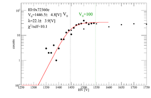
Gains for each PMT/base combination have been tested. We placed two trigger paddles on top of each other, and varied the HV on the one we are testing, while keeping the other held at 1700 V. The coincidence rates for cosmic rays were taken, and plotted against HV. The figures are here:Gain Adjustments, with a table of HV values.
Links
- Proposal Document on GlueX docDB (contains 1 page executive summary)
- Kei Moriya Talk at GlueX Collaboration Meeting 2011 October@JLab
- Hall B HD-ICE webpage
- Hall B HD-ICE wiki, with link to run schedule
Personnel Available for Datataking
- IU
- Kei Moriya (time centered around November 7th not available due to birth of child)
- Regina
Operating Safety Procedure
OSP can be found at PHY-11-040-0SP
Links to EHS&Q manual:
- Chapter 3310 Operational Safety Procedure Program
- Chapter 3210 - Work Panning, Control and Authorization
How to run DAQ
You can find some instructions on how to run DAQ in the HDFCALEST electronic log book or in the trigger page.
